Vegabar 81, flange connection, dimensions in inch, 9 supplement – VEGA VEGABAR 81 Save sensor - Operating Instructions User Manual
Page 53
53
9 Supplement
VEGABAR 81 • Slave sensor for electronic differential pressure
45049-EN-131011
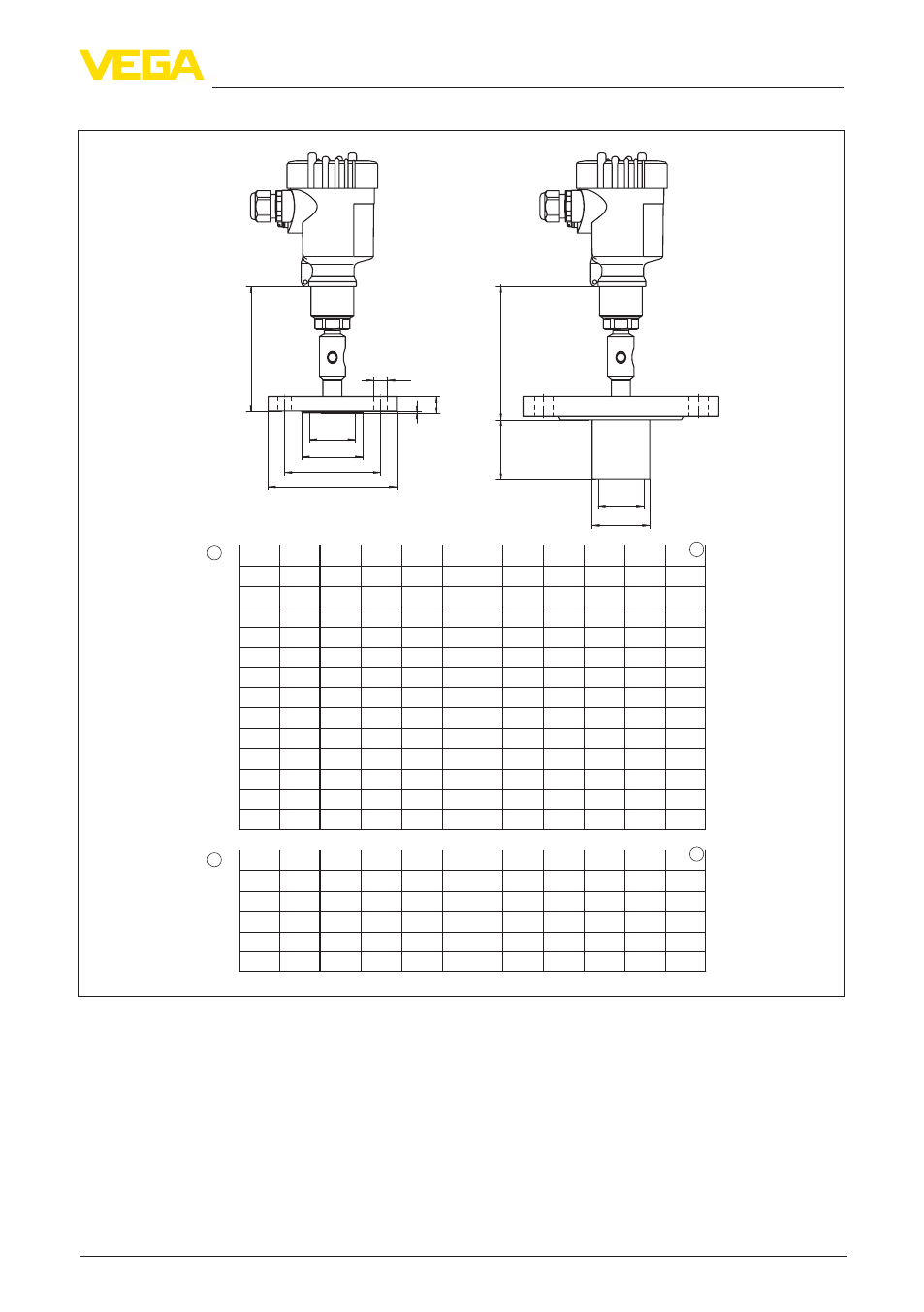
VEGABAR 81, flange connection, dimensions in inch
DN
PN
D
k
b
25
40
4.53" 0.71" 3.35"
40
40
5.91" 0.71" 4.33"
50
40
6.5" 0.79" 4.92"
d2
4 x ø0.55"
4 x ø0.71"
4 x ø0.71"
d4
2.68"
3.47"
4.02"
f
0.08"
0.08"
0.08"
80
40
7.87" 0.95" 6.3" 8 x ø0.71" 5.43" 0.08"
50
40
6.5" 0.79" 4.92"
50
40
6.5" 0.79" 4.92"
80
40
7.87" 0.95" 6.3"
4 x ø0.71"
4 x ø0.71"
8 x ø0.71"
4.02"
4.02"
5.43"
0.08"
0.08"
0.08"
RL
-
-
-
3.94"
1.97"
7.87"
-
d5
-
-
-
2.99"
1,9"
1,9"
-
dM
1.26"
20
40
4.13" 0.71" 2.95" 4 x ø0.55" 2.28" 0.08"
-
-
-
32
40
5.51" 0.71" 3.94" 4 x ø0.71" 3.07" 0.08"
-
-
-
1.77"
2.32"
2.84"
80
40
7.87" 0.95" 6.3" 8 x ø0.71" 5.43" 0.08" 7.87" 2.99" 2.84"
1"
150
80
40
7.87" 0.95" 6.3" 8 x ø0.71" 5.43" 0.08" 1.97" 2.99" 2.84"
-
-
-
2"
150
"
lbs
D
b
k
d2
d4
f
RL
d5
dM
-
-
-
2"
150
2"
1.9" 1.85"
3"
150
-
-
-
3"
150
4.33"
5.91"
5.91"
7.48"
7.48"
2.01"
3.62"
3.62"
5"
5"
0.08"
0.08"
0.08"
0.08"
0.08"
0.57"
0.77"
0.77"
0.96"
0.96"
3.13"
4.75"
4.75"
6"
6"
6"
2.99" 2.84"
1.85"
50
40
6.5" 0.79" 4.92" 4 x ø0.71" 4.02" 0.08" 3.94" 1,9" 1.85"
1.85"
3.5"
100
40
9.25" 0.95" 7.48" 8 x ø0.87" 6.38" 0.08" 3.94" 3.70" 3.5"
3
3
1
2
4 x ø0.63"
4 x ø0.75"
4 x ø0.75"
4 x ø0.75"
4 x ø0.75"
HU
NE
I2
I5
NC
I7
ID
IG
IE
IF
BW
CA
F3
CB
RL
d5
dM
dM
115 mm (4.53"
)
109 mm (4.29"
)
D
d4
d2
f
b
k
Fig. 29: VEGABAR 81, flange connection, dimensions in inch
1 Flange connection according to DIN 2501
2 Flange connection according to ANSI B16.5
3 Diaphragm diameter