5 wiring plan, double chamber housing ex d – VEGA VEGAPULS 62 (≥ 2.0.0 - ≥ 4.0.0) Foundation Fieldbus User Manual
Page 31
31
5 Connecting to the bus system
VEGAPULS 62 • Foundation Fieldbus
36506-EN-121011
+
Bus
2
3
1
2
( )
(-)
1
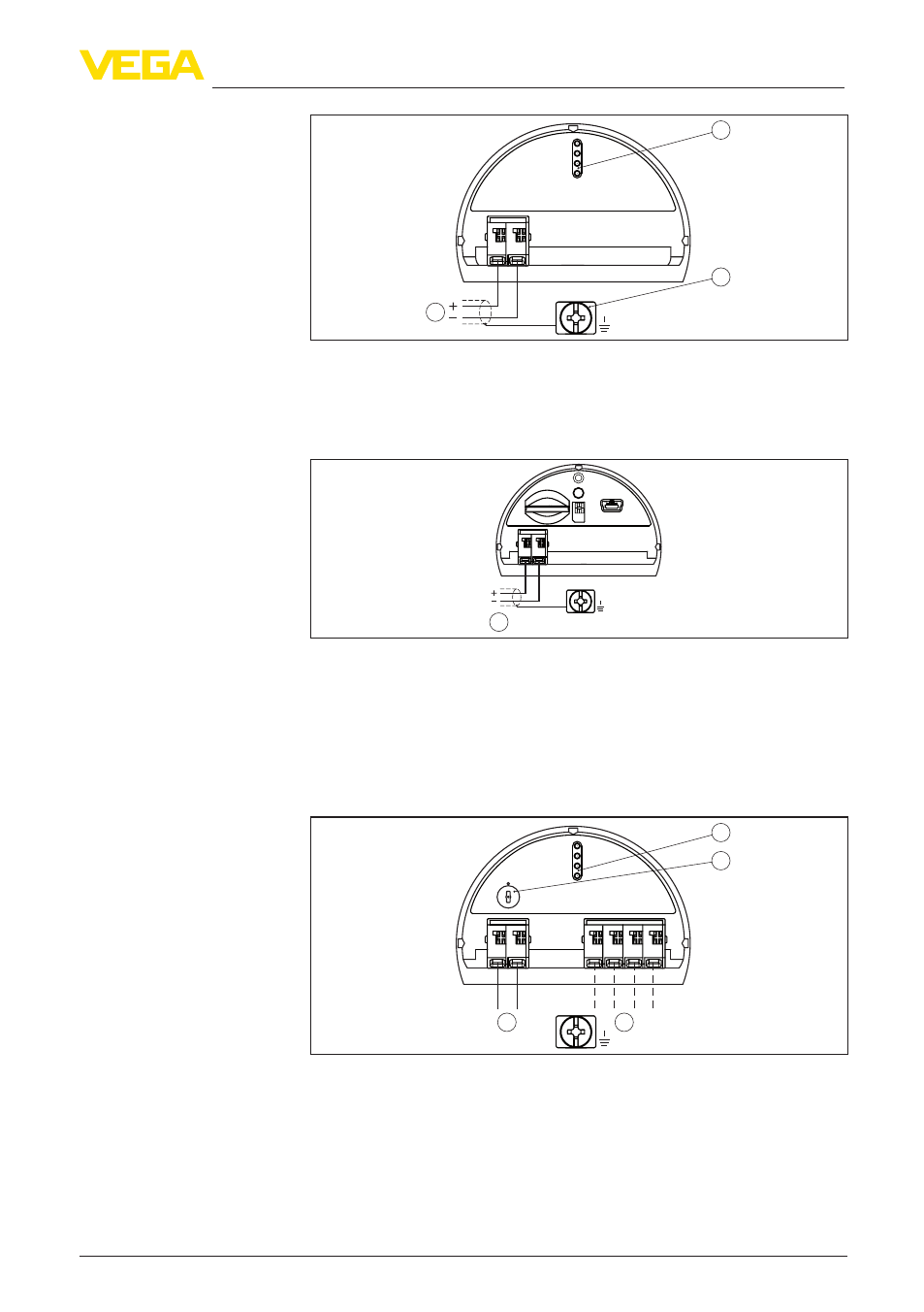
Fig. 28: Connection compartment, double chamber housing
1 Voltage supply, signal output
2 For indicating and adjustment module or interface adapter
3 Ground terminal for connection of the cable screen
1
Bus
USB
Status
Test
SIM-Card
1
2
+
( )
(-)
Fig. 29: CConnection of the voltage supply of the radio module
1 Voltage supply
You can find detailed information for connection in the supplementary
instructions "PLICSMOBILE GSM/GPRS radio module".
5.5 Wiring plan, double chamber housing Ex d
5
0
1
0
1
+
6 7 8
Bus
2
3
1
2
( )
(-)
4
1
Fig. 30: Electronics compartment, double chamber housing
1 Internal connection to the connection compartment
2 Contact pins for the indicating and adjustment module or interface adapter
3 Simulation switch ("1" = mode for simulation release)
4 Internal connection to the plug connector for external indicating and adjust-
ment unit (optional)
Connection compartment
Radio module PLICSMO-
BILE integrated in the
connection compartment
Electronics and connec-
tion compartment