VEGA VEGAFLEX 66 (-200…+400°C) 4 … 20 mA_HART two-wire User Manual
Page 43
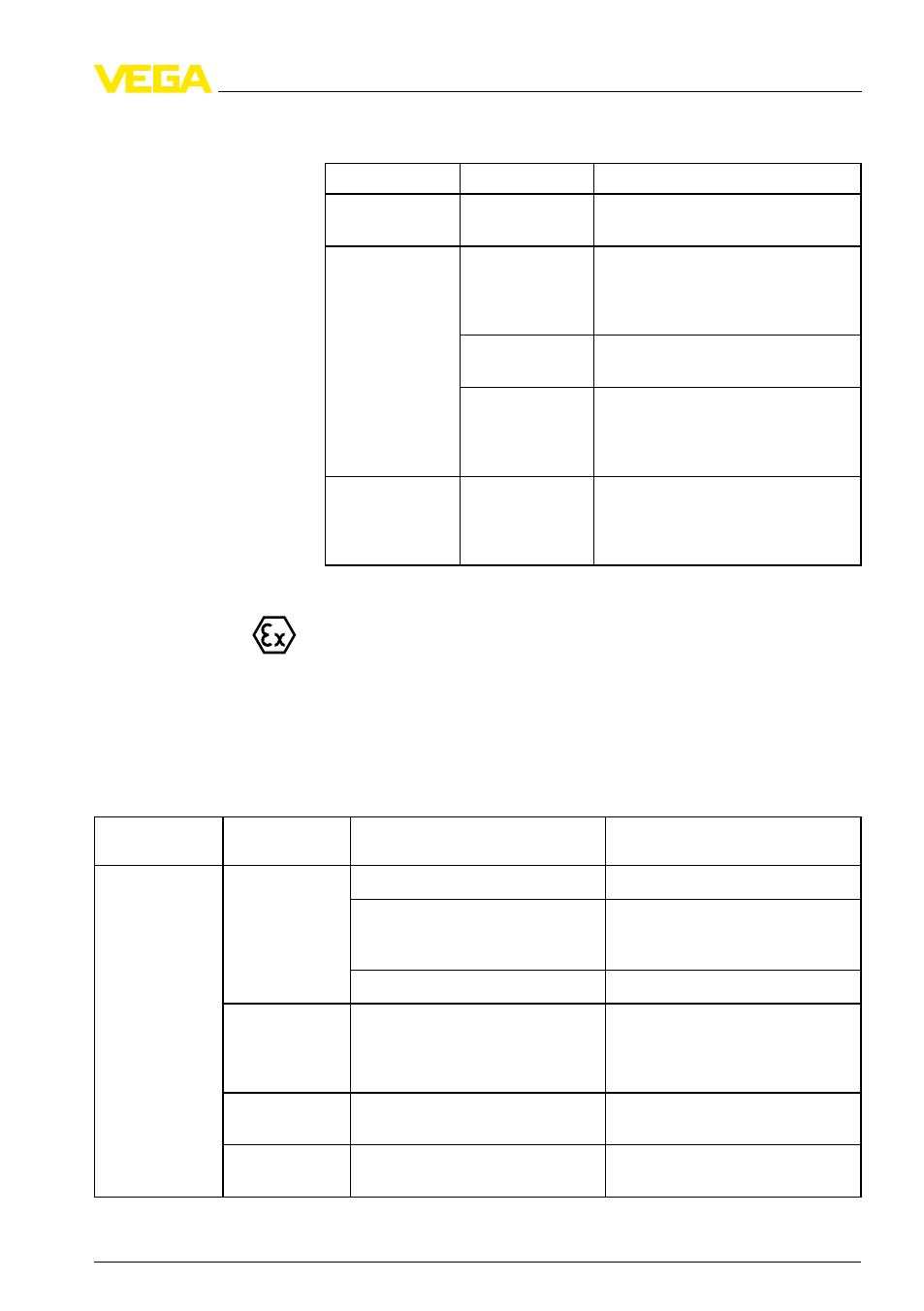
Error
Cause
Removal
4 … 20
mA signal
not stable
L
evel fluctuations Set damping via the indicating and
adjustment module
4 … 20
mA signal
missing
E
lectrical con-
nection faulty
C
heck connection according to chap-
ter "
Connection steps
"
and if ne-
cessary, correct according to chapter
"
Wiring plan
"
V
oltage supply
missing
C
heck cables for breaks; repair if
necessary
O
perating voltage
too low or load
resistance too
high
C
heck, adapt if necessary
C
urrent signal
greater than 22 mA
or less than
3.6
mA
O
scillator in the
sensor defective
E
xchange the instrument or send it in
for repair
I
n Ex applications, the regulations for the wiring of intrinsically safe
circuits must be observed.
T
he indicating and adjustment modules indicates faults via error codes
and text messages. The following table describes the error codes with
status according to NE 107 and gives information on the causes of
failure and their removal:
Status accor-
ding to NE 107
Error code
Text message
Cause/Rectification
F
ailure
E
013
no measured value available
S
ensor in boot phase
no measured value available
S
ensor does not find an echo, e.g.
due to faulty installation or wrong
parameter adjustment
no measured value available
W
rong sensor length entered
E
017
A
djustment span too small
A
djustment not within the specifica-
tion. Carry out the adjustment again,
increasing the distance between
min. and max. adjustment
E
036
N
o operable software
F
ailed or interrupted software up-
date/Repeat software update
E
042
H
ardware error, electronics defec-
tive
E
xchange the instrument or send it
in for repair
Error messages via the
indicating and adjust-
ment module
VEGAFLEX
66 • 4 … 20
mA/HART two-wire
43
8 M
aintenance and fault rectification
34173
-
EN
-100427