VEGA VEGAFLEX 67 (-40…+150°C PFA insulated) Profibus PA User Manual
Page 46
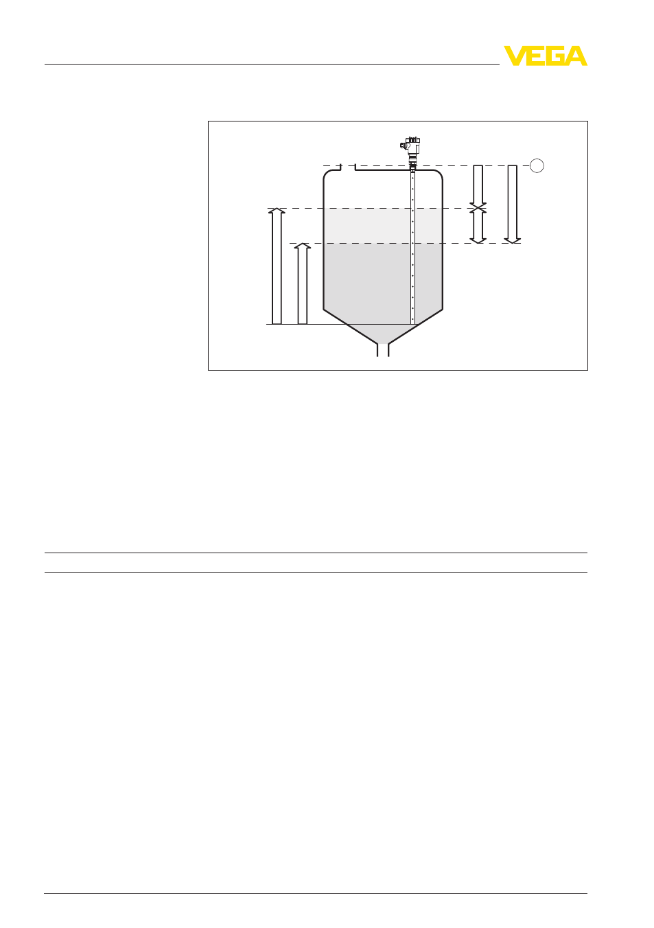
TS
d1
h1
h2
d2
1
L2
L1
Fig. 19: Interface measurement (interface is between L1 and L2)
1
Reference plane
d1 Distance to the interface (Secondary Value 2)
d2 Distance to the level (Distance Level)
TS
Thickness of the upper medium (d1 - d2)
h1 Height - interface (Secondary Value)
h2 Height - Level
L1
Lower medium
L2
Upper medium
Resolution, digital
>
1 mm (0.039 in)
Accuracy (according to DIN EN 60770-1)
Process reference conditions according to DIN EN 61298-1
-
Temperature
+
18 … +30 °C (+64 … +86 °F)
-
Relative humidity
45 … 75 %
-
Air pressure
+
860 … +1060 mbar/+86 … +106 kPa
(+12.5 … +15.4 psig)
-
Emulsion phase
<
2 mm (< 0.079 in)
Installation reference conditions
-
Min. distance to installations
>
500 mm (19.69 in)
-
Vessel
metallic, ø 1 m (3.281 ft), centric installation,
process fitting flush with the vessel ceiling
-
Medium
Water/Oil (dielectric figure ~2.0)
-
Installation
Probe end does not touch the vessel bottom
Sensor parameter adjustment
Gating out of false signals carried out
In bulk solids applications, implementing a false
signal suppression is generally not recommended.
The accuracy of bulk solid applications depends
46
VEGAFLEX
67 • Profibus PA
10 Supplement
32305
-EN
-120329