3 wiring plan, Terminal assignment, Designation terminal assign- ment input and output – VEGA VEGATRENN 149A Ex User Manual
Page 16
16
5 Connecting to power supply
VEGATRENN 149A Ex • Ex-separator for 4 … 20 mA/HART
24816-01-131025
Sensor circuit (Ex area)
The sensor must be connected to the blue
connection terminals I+ and I-. The sensor
circuit of the separator VEGATRENN 149A Ex is
separated from the processing circuit.
The sensor circuit is active, this means that the
connected sensor is powered by VEGATRENN
149A Ex.
I -
I +
+
-
I
+
I
1
2
Abb. 9: Connection sensor circuit
1 Ex area
2 Non-Ex area
Processing circuit (non-Ex area)
Processing systems such as e.g. an indicating
instrument or a PLC system are connected to
terminals O+/O-/O+H.
If a HART handheld or an interface adapter VE-
GACONNECT is connected to the communica-
tion sockets in the front, the processing system
must be connected to terminals O+H and O-.
The resistance necessary for HART commu-
nication is already integrated in VEGATRENN
149A Ex with this version. Keep in mind that
in this case the max. connectable load or load
resistance is reduced (see "Technical data" in
the "Supplement").
0-
0+
Hart
0+H
0
+
0
OK
VEGADIS 175
Abb. 10: Connection example with HART communi-
cation
0+
0-
0+H
0
+
0
OK
VEGADIS 175
Abb. 11: Connection example without HART commu-
nication
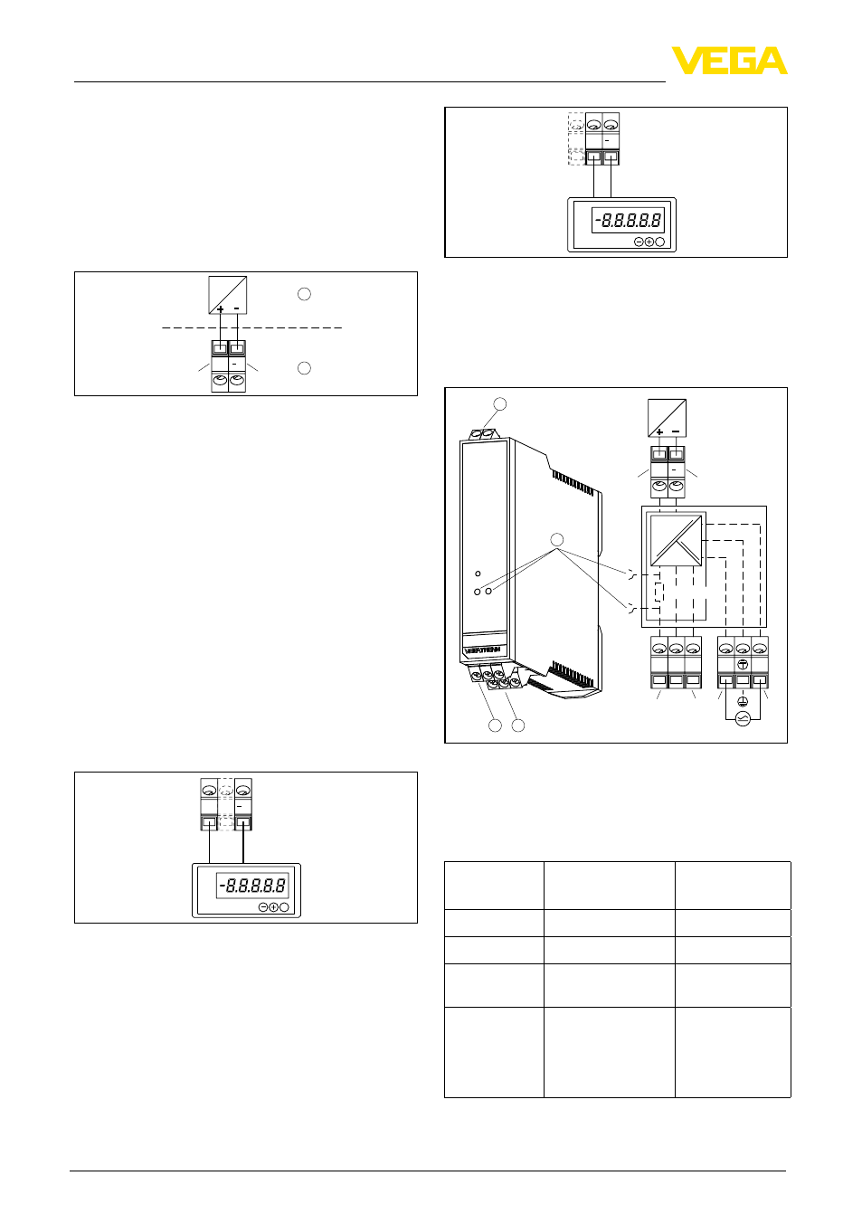
5.3 Wiring plan
Terminal assignment
0+
0+
Hart
0 –
on
CONNECT
I –
I +
0–0+
I
+
I
0+H
N/–
L/+
+
–
L/+
N/–
1
2
3 4
Abb. 12: Wiring plan VEGATRENN 149A Ex
1 Sensor circuit
2 HART communication socket
3 Processing circuit
4 Voltage supply
Designation Terminal assign-
ment
Input and
output
L/+
L (AC), + (DC)
Voltage supply
N/-
N (AC), - (DC)
Voltage supply
Grounding
Protective conduc-
tor PE
Voltage supply
O+
O-
O+H
Measuring signal +
Measuring signal -
Measuring signal +
with HART resistor
Measuring sig-
nal processing
circuit "Non-Ex
area"