Adjustment example 3, Adjustment example 4, Setup – VEGA VEGATOR 622 User Manual
Page 16
16
VEGATOR 620 … 622
Setup
12 13 14
t
12 13 14
Level/Pressure
Switching
points
Mode A
Mode B
Transistor
conductive
blocked
conductive
blocked
Min. level
Max. level
12 13 14
t
12 13 14
12 13 14
12 13 14
Level/Pressure
Switching
points
Mode A
Mode B
Transistor
conductive
blocked
conductive
blocked
Mode A
Mode B
conductive
blocked
conductive
blocked
2nd VEGATOR
1st VEGATOR
Level 1
1st VEGATOR…
Level 2
2nd VEGATOR…
Level 2
Level 1
Min. level
Max. level
Rel.
Rel.
• Turn the potentiometer (1) very slowly
clockwise until the status indication (2)
changes, i.e. lights in mode A, extinguishes
in mode B. Note the position of the potenti-
ometer.
• Determine the average value and adjust it
on the potentiometer (1).
• The signal conditioning instrument is now
ready for operation.
Please close with the transparent cover
(15).
The relay and transistor output as well as the
status indication behave in mode A and B as
previously shown in „Adjustment example 1“,
see top left.
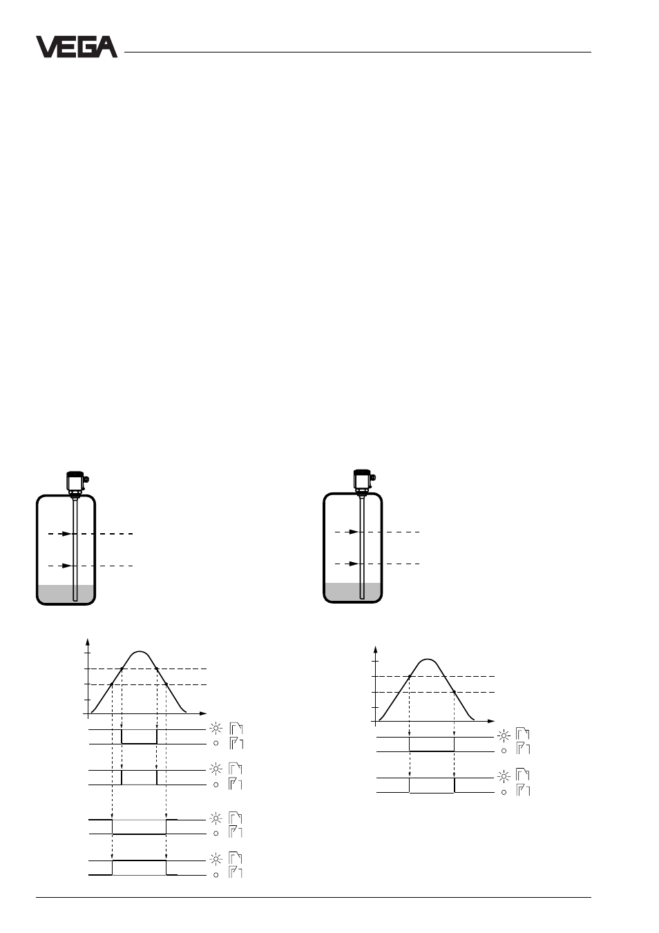
Adjustment example 3
- two VEGATOR 620
- as dual single point control (see „3.3
Connection plans, extension example“)
- vertically mounted capacitive measuring
probes
Procedure
• Set the potentiometers (1) of the two signal
conditioning instruments to 10.
• Fill the vessel up to level 1.
• Turn the potentiometer (1) of the first VE-
GATOR … very slowly anticlockwise until
the status indication (2) changes, i.e. lights
in mode B, extinguishes in mode A.
• Now fill the vessel up to level 2.
• Now turn the potentiometer (1) of the sec-
ond VEGATOR … very slowly anticlockwise
until the status indication (2) changes, i.e.
lights in mode B, extinguishes in mode A.
• The two signal conditioning instruments are
now ready for operation.
Please close each with the transparent
cover (15).
Adjustment example 4
- VEGATOR 622
- double point control
- sensors: vertically mounted capacitive
meas. probes or hydrostatic pressure
transmitters