3 electrical connection, Electrical connection – VEGA VEGATOR 537 Ex User Manual
Page 8
8
VEGATOR 537 Ex
23465-EN-030723
Electrical connection
3 Electrical connection
Danger
Switch off the power supply before starting
connection work. Connect mains voltage acc.
to the following connection diagram.
When connecting to supply voltage or recon-
necting the sensor, the instrument is sub-
jected to a function test. See also "5.1
Recurring test acc. to WHG".
If only one channel is used on VEGATOR
537 Ex signal conditioning instrument, con-
nect a resistor of 1 k
Ω
(0.5 W) to the unused
connection pins of the second channel. The
resistor prevents a fault signal, caused by a
missing sensor, from being triggered.
A transistor output operating in parallel is
available for each relay output.
Note
If very strong electromagnetic interference is
expected, we recommend the use of
screened cable. The screen of the cable
must only be earthed at one end. Carry out
the earthing on the sensor side.
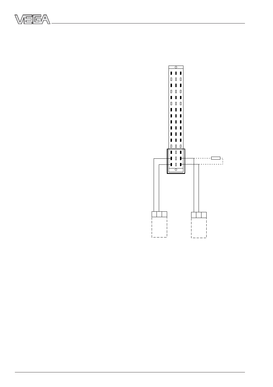
The following connection plan shows the
currentless condition.
Sensor 1
1
2
3
Sensor 1
1
2
3
2
4
6
8
12
20
28
24
22
10
14
16
18
30
32
d b z
26
1 k
Ω
resistance with
unused channel
Ex separat-
ing chamber
Sensor
Channel 1
Sensor
Channel 2
Module with multipoint connector acc. to
DIN 41 612 for carrier (rear view)