Ex version, Coding, Mounting – VEGA VEGATOR 537 Ex User Manual
Page 7: Fig. 2.8 module 33 (ex)
VEGATOR 537 Ex
7
23465-EN-030723
Mounting
o 9 o
o 1 o
a c
VEGATOR 537
c23
o 3 o
o 5 o
o 7 o
o11o
o13o
o15o
c7
o17o
o19o
o21o
o23o
o25o
o27o
o29o
o31o
z b d
Ex coding
VEGATOR
Ex version
Ex separating chamber
An Ex separating chamber must be mounted
to the connections of VEGATOR to ensure
sufficient "air and creep distances". Feed the
cables through the Ex separating chamber
and connect them. Fasten the Ex separating
chamber with the lower retaining screw. Note
the operating instructions of the carrier BGT
596.
Mounting in carriers
If you are mounting a VEGATOR with Ex
approval in an assembly carrier, you must
use a VEGA-Ex module. Leave a distance of
min. 10 mm (2 TE) to modules of other manu-
facturers. If VEGATOR is to be mounted in
the carrier at the extreme left position, a blind
cover with min. 20 mm (4 TE) must be
mounted to the left of the module.
Protection for Ex applications
For Ex applications, protection IP 20 must be
maintained. To do this, cover gaps and
empty slots with blind covers.
Fig. 2.9
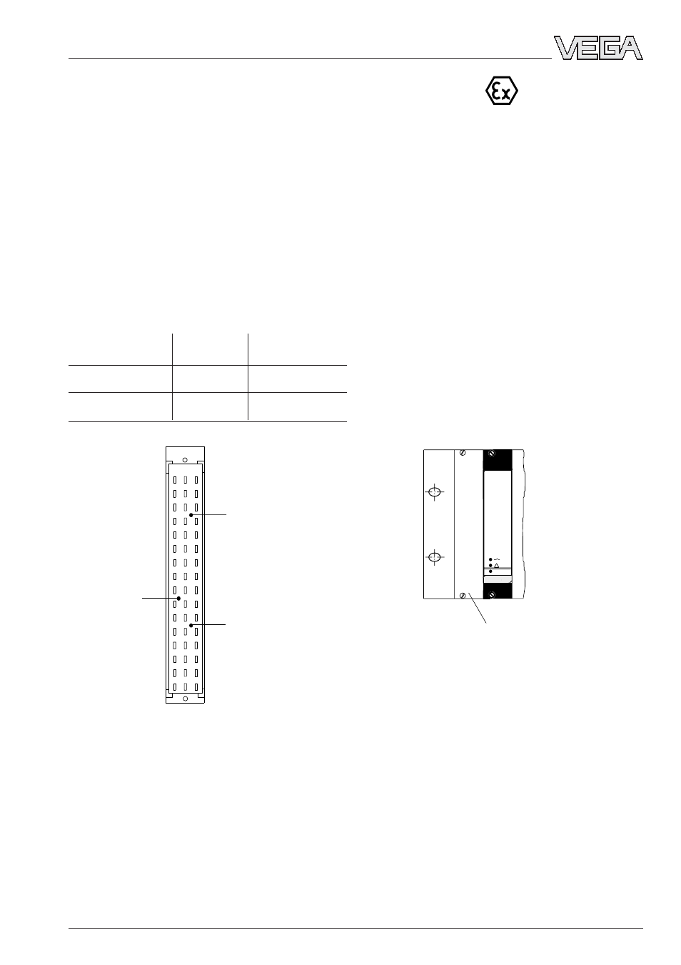
Coding
The multipoint connector of the instrument is
provided with one or more coding holes to
prevent incorrect module insertion.
A fixed coded pin on the Ex module ensures
that only Ex instruments can be inserted.
Two additional coded pins are enclosed with
the module to prevent incorrect insertion of
other instruments. Insert the attached coded
keys into the holes on the multipoint connec-
tor. The coded keys must be plugged into
the following positions:
Instrument
Ex coding
coding
VEGATOR 537
a19 / c7
––
VEGATOR 537 Ex
a19 / c7
c23
Fig. 2.8 Module 33 (Ex)
on
2
VEGATOR
Blind cover