5 diagnosis, 1 recurring test acc. to whg, 2 exchange of electronics – VEGA VEGASWING 83A EXD User Manual
Page 25
VEGASWING 81A EXD and 83A EXD
25
5.2 Exchange of electronics
• Interrupt the voltage supply and discon-
nect the connection lines and the switching
current circuit on the switching cabinet.
• Make sure that there is no Ex-atmosphere.
• Loosen the four screws of the housing
cover with a screwdriver and remove the
cover.
• Disconnect the connection lines on the
oscillator.
• Remove the old oscillator and insert the
new one.
• Set the A/B-switch to the same position as
on the old oscillator (not with SWING
E82 Z).
• Set the potentiometer for the density ad-
justment of the new electronics to the same
value as on the old oscillator.
• Fasten the housing cover and remove the
screw on the electronics box. Note that the
screw head is turned in one of the open-
ings.
• Switch on the power supply . The sensor is
immediately ready for operation.
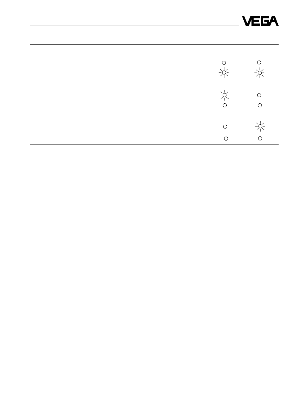
Test course
A-mode
B-mode
1 Simulation of a fault signal (after release of key approx. 3 s)
1)
Level relay
deenergized > 22 mA
2)
Failure relay
deenergized < 2,2 mA
2)
2 Simulation of an empty signal (approx. 1,5 s)
Level relay
energized
8 mA
2)
Failure relay
energized
3 Simulation of a full signal (approx. 1,5 s)
Level relay
deenergized 16 mA
2)
Failure relay
energized
4 Return to the actual operating condition (covered/uncovered)
1)
as long as the key is pushed, the instrument signals failure.
2)
condition of VEGASWING
With the provided current values, you can also carry out the function test directly via a DCS or
a processing system
Diagnosis
• Connect the connection lines again.