3 electrical connection – VEGA VEGASWING 83A EXD User Manual
Page 18
18
VEGASWING 81A EXD and 83A EXD
Mounting not
suitable for
adhesive prod-
ucts
Fig. 2.7
Installation examples
Welded socket
VEGASWING has a defined begin of the
thread. This means that each VEGASWING is
in the same position after screwing in. There-
fore remove the supplied seal from the
thread of VEGASWING. This seal is not re-
quired when using a welded socket. Screw
VEGASWING into the welded socket.
You can deter mine the later position of
VEGASWING already before welding (see
fig. 2.2). Mark the appropriate position of the
welded socket. Before welding you have to
unscrew VEGASWING and remove the rub-
ber ring out of the welded socket.
Optionally a welded socket is available which
is already provided with a marking. Weld this
welded socket with the marking to the top
(see fig. 2.6).
Fig. 2.6
Marking
Mounting, electrical connection
3 Electrical connection
Danger
Switch off the power supply before starting
connection work.
The electrical connection must be carried out
dependent on the integral oscillator . Connect
mains voltage according to the following
connection diagrams. Note the following
special instructions for electrical connection in
Ex-areas.
When connecting the voltage supply or re-
connecting the sensor , the instrument passes
the function test (only with oscillator
SWING E82Z and connected signal condi-
tioning instrument). See also "5.1 Recurring
test acc. to WHG “.
Note
If strong electromagnetic interferences have
to be expected, we recommend to use
screened cable for the Z-electronics. The
screening of the cable must be earthed on
the sensor side (VEGASWING) via the inter -
nal earth terminal.
Generally connect VEGASWING with P A. Use
the earth connection terminal on the housing.
• Interrupt all lines to the sensor (voltage
supply and signal lines) on the switching
cabinet.
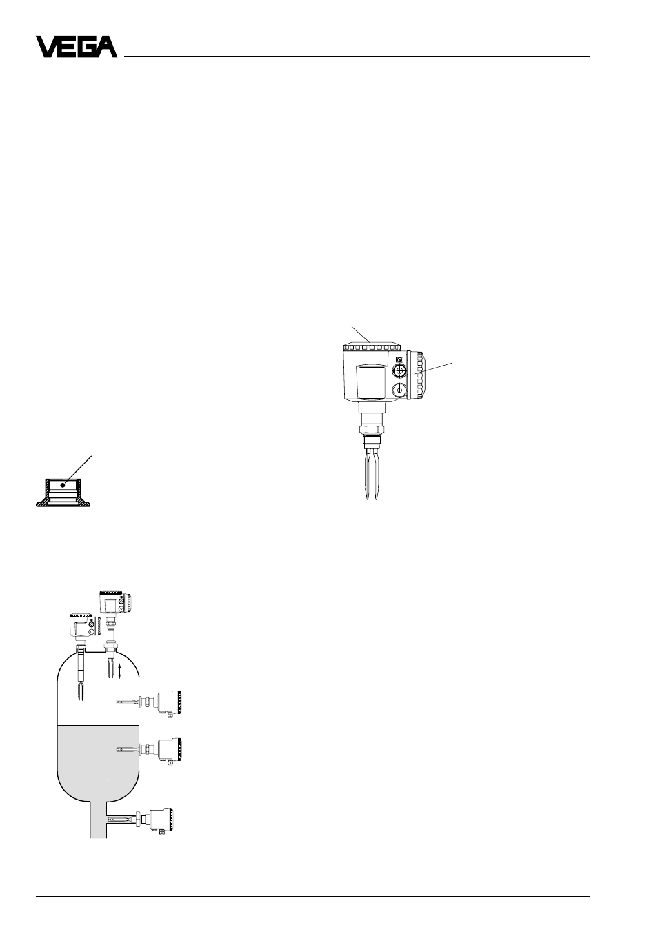
Fig. 2.8
Connection box
(small cover)
Electronics box (large cover)