Parts and functions 2. unit mounting – V-Tech C5-MDS Info User Manual
Page 2
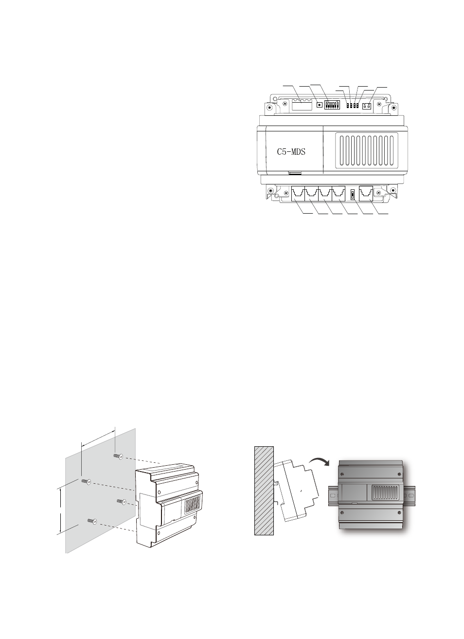
1. Parts and Functions
2. Unit Mounting
109mm
124mm
Direct Wall Mounting
DIN Rail Mounting
JWB(IN4) JWB(IN3) JWB(IN2) JWB(IN1)
SW1 JWB(OUT)
PA
JWP
S1
POWER
ERROR
IN-USE
LINK
RS-485
*
POWER: Power indicator. Always ON
while working.
*
LINK: Signal indicator. Flicker means
signal is transmitted in bus, always ON
means communication ERROR in bus.
*
IN-USE: Status Indicator. ON while
working.
*
ERROR: Error indication. ON when
equipment failure.
*
JWB (OUT): Output port. RJ45 port,
connected to C5-IPC.
*
JWP: Power input. P+, positive 18V; P-,
negative.
*
JWB (IN1, IN2, IN3, IN4): Connected to door stations (Max.4).
*
PA: Test button. Press PA, the IN-USE indicator will light, and then start to monitor door station
connected circular with click of relay.
*
S1: DIP Switch function setting, refer to DIP switch setting.
*
SW1: Always set to the 2V, 2A position.
*
JTAG: update port. Connected to PC to update the firmware of C5-MDS
*
RS-485: PC port. To update the firmware of C5-MDS.