Parts and functions 2. unit mounting, Gp-acs – V-Tech GP-ACS Info User Manual
Page 2
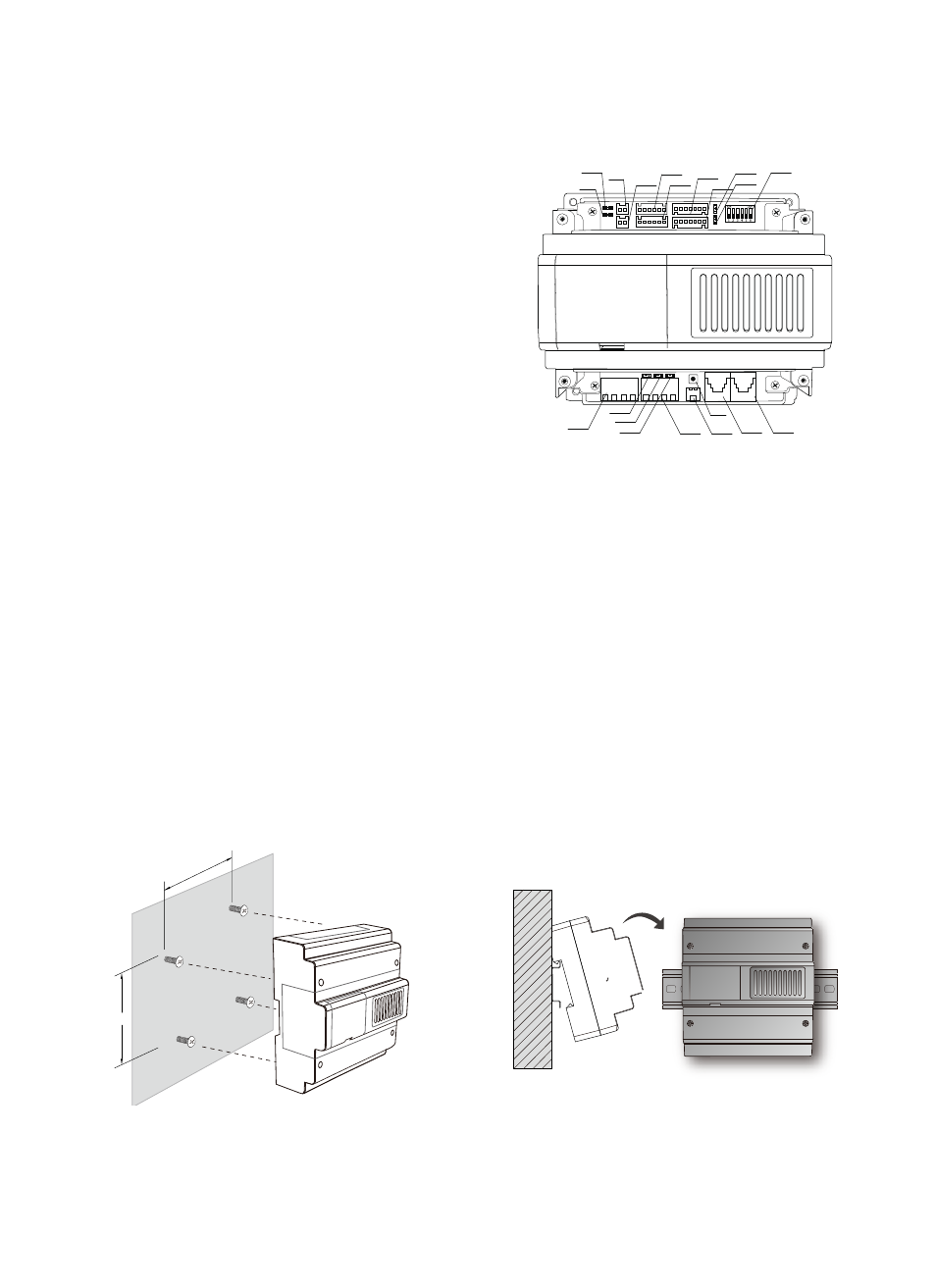
1. Parts and Functions
2. Unit Mounting
109mm
124mm
Direct Wall Mounting
DIN Rail Mounting
GP-ACS
JWP
JWB(IN) JWB(OUT)
POWER
LINK
IN-USE
JWB(IN) RS485
PA
JP-LK1
CN-DS1-1
CN-DS1-2
JP-LK2
CN-LK1
CN-LK2
CN-RD1
LED1
CN-RD2
LED2
S1
*
Power: Power indicator, always ON while
working
*
LINK: Signal indicator, flicker means signal
is transmitted in the bus line
*
IN-USE: Status indicator, ON while working
*
LED1: Indicators for first group of card
reader
*
LED2: Indicators for second group of card
reader
*
JWP: Power input, DC 18V
*
RS485: PC port, to set the parameters of
GP-LIFT
*
CN-NET: Signal input and output, RJ45 port, connected to C5-MDS
*
PA: Test button, used for card management without connecting to LAN
*
S1: DIP switch
*
CN-RD1, CN-RD2: Card reader connection port, connected to independent card reader
*
CN-LK1, CN-LK2: Lock connection port, connected to lock and outlet button
*
CN-DSI-1, CN-DSI-2: Door status detection
*
JP_LK1, JP_LK2: Lock jumper for lock type selection