Veris Verabar V450 Installation Instructions User Manual
Page 4
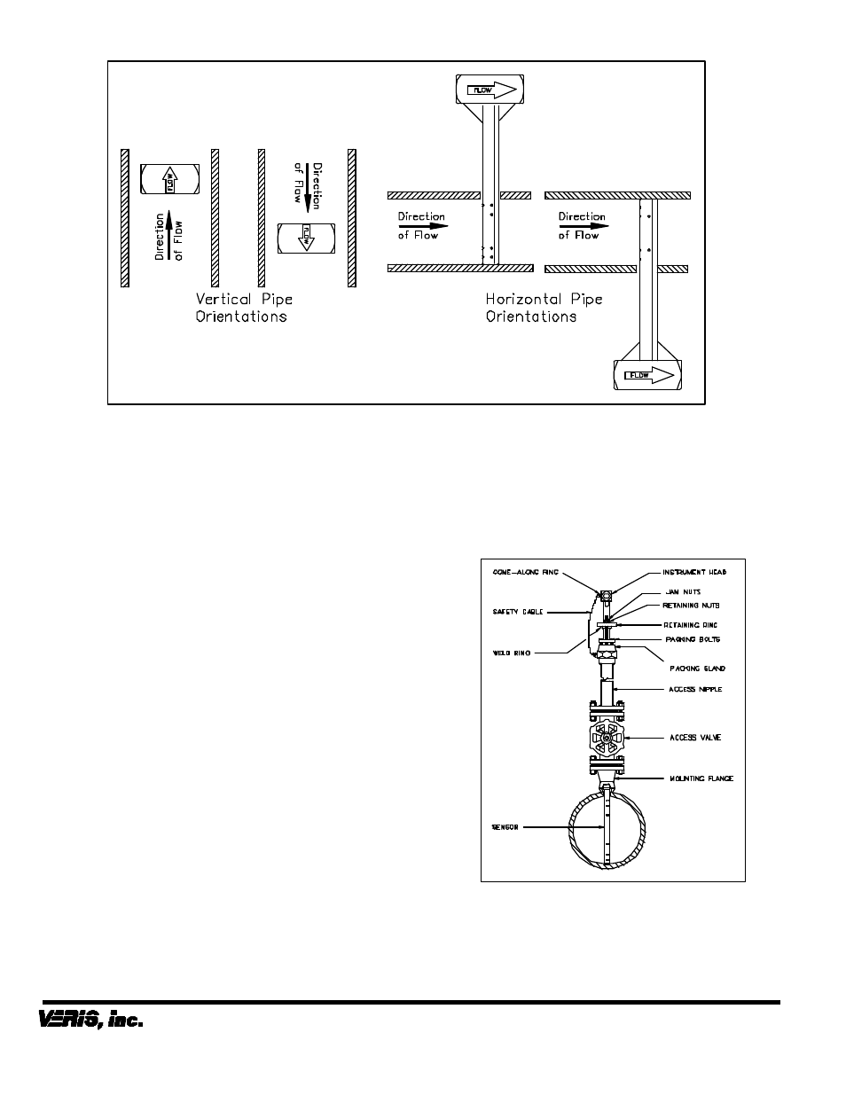
Figure 7. Orientation of Flow Arrow
•
Once the sensor is completely bottomed, slide the
retaining ring over the three retaining studs and
tighten the retaining nuts. The retaining nuts
should be tightened until the ring presses firmly
against the weld ring. (This will prevent the sensor
tip from vibrating free from the opposite wall of the
pipe). Jam nuts should now be threaded on and
pressed tightly against the retaining nuts.
Warning: The retaining ring must be secured
before the come-along is removed.
•
At this point, the come-along can be safely
removed.
•
Re-verify that the orientation of the sensor is such
that the arrow labeled “flow” on the instrument
head is in the direction of the flow in the pipe to
within 3° (Figure 7).
Warning: The retaining ring should not be removed
unless a come-along is properly attached and all
slack is removed from the come-along.
The Verabar is now properly installed (Figure 9).
Periodic Maintenance
The assembly should be periodically checked. Verify
that no leaks are present. Tighten the packing bolts if
necessary.
Sensor Removal Procedure
•
Shut off instrument valves.
•
Properly install a come-along and remove all slack
from the come-along.
•
Remove jam nuts, then remove retaining nuts and
pull retaining ring off retaining studs.
•
Retract the sensor until the safety cable is tight.
•
Completely shut off the access valve. Slowly
crack open one of the Verabar instrument valves
and bleed off any remaining pressure contained in
the access nipple. The sensor assembly can now
be removed.
Figure 9. Installed V450
6315 Monarch Park Place
•
Niwot, CO 80503 USA
•
Phone: (303) 652-8550
IO
-450 VWI-CS-029 REV B (6/08)
Fax: (303) 652-8552
•
Email: [email protected]
•
Website: www.veris-inc.com
Printed in USA