Veris Verabar V250 Installation Instructions User Manual
Page 3
5.3
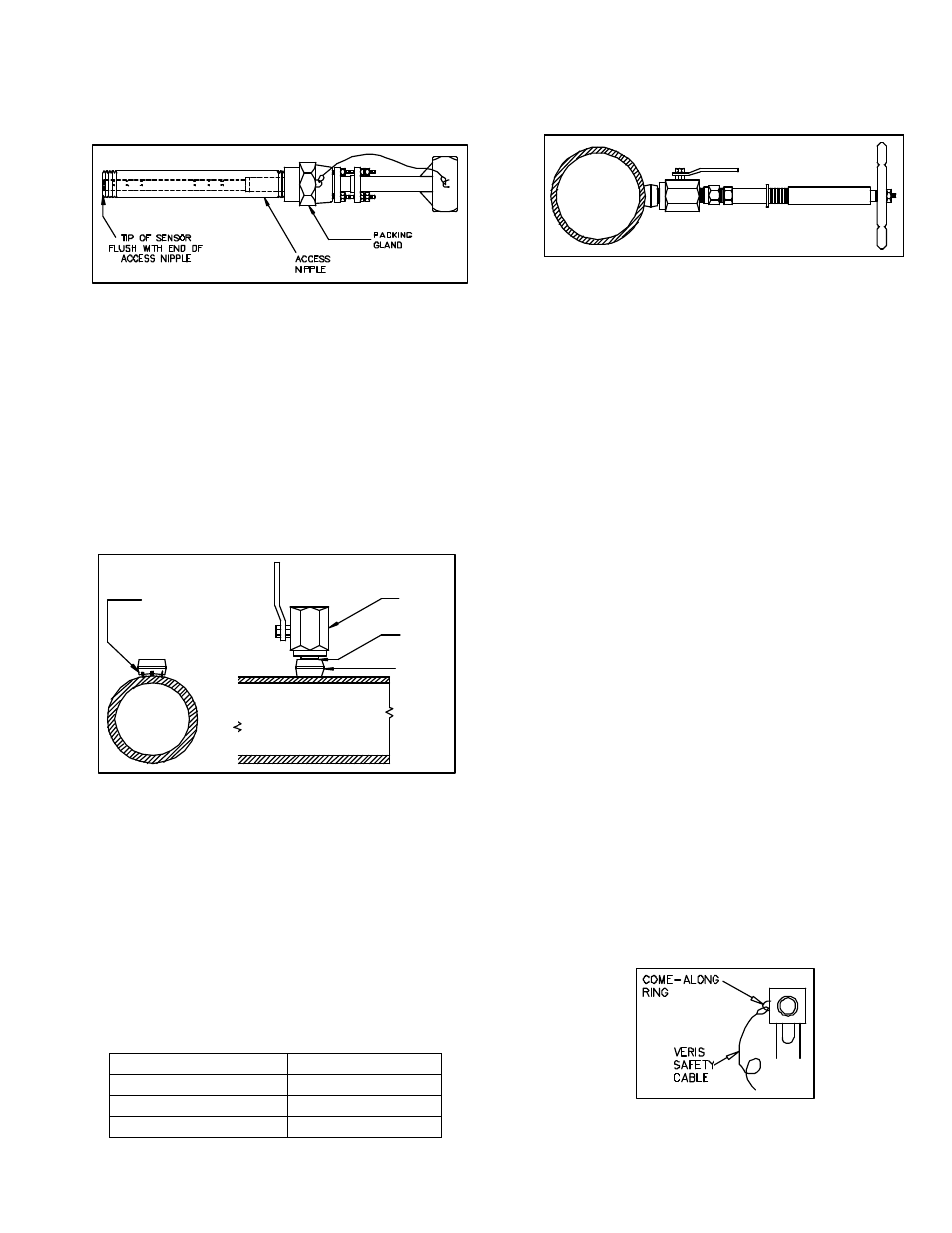
Install Access Nipple
Using proper sealant, thread access nipple into packing
gland (Figure 3). Note that the lower clamp ring on the
access nipple is nearest the tip of the Verabar.
Figure 3. Thread Access Nipple into Packing Gland
5.4
Tighten Packing
Retract the Verabar such that the tip of the sensor is
flush with the end of the access nipple (Figure 3).
Tighten the three packing bolts on the packing gland.
5.5
Weld Threadolet to Pipe
Mark the location where the Verabar is to be mounted.
Position the threadolet over the center of the mark.
Using the appropriate weld gap (1/16” [1.5mm] typical),
tack weld the threadolet into position. Protect threads
on the threadolet, then finish welding the threadolet to
the pipe per applicable codes (Figure 4).
Figure 4. Weld Gap
5.6
Install Close Nipple & Access Valve
Using appropriate pipe thread sealant, install close nipple
and access valve (Figure 4). Be sure the valve handle
does not hit the pipe during opening and closing of the
valve. Verify that the close nipple and access valve are
properly tightened, because beyond this point it will not
be serviceable without depressurizing the line.
5.7
Drill Hole in Pipe
•
With the access valve in the full open position,
install an appropriate Hot-Tap Drilling Machine
(Figure 5) and drill a hole in the pipe (hole sizes
per the chart below). Follow the instructions given
by the Hot-Tap Drilling Machine.
Sensor Size
Hole Dia
V250-05
½” (13mm)
V250-10
1” (25mm)
V250-15
1-1/2” (38mm)
•
After the hole has been completely drilled, retract
the Hot-Tap Drilling Machine. Shut off the access
valve prior to removal of the Hot-Tap Drilling
Machine.
Figure 5. Hot Tap Drilling Machine
Note: There are numerous Hot Tap Drilling Machines on
the market with various pressure and temperature
ratings. These devices can usually be rented at a local
utility company. For more information concerning Hot
Tap Drilling Machines, the following companies can be
contacted: Mueller Co., Decatur, IL (217) 423-4471 or
T.D. Williamson, Inc., Tulsa, OK (918) 446-1941.
5.8
Mount Sensor Assembly to Access
Valve
Apply appropriate thread sealant to the access nipple
and thread the access nipple into the access valve.
Orient the sensor such that the arrow labeled “flow” on
the instrument head is in the direction of the flow in the
pipe to within 3° (orientation per Figure 7).
5.9
Vent Access Valve to Verify No
Leaks Are Present
With the instrument valves shut, slowly crack open the
access valve and verify there are no process fluid leaks.
If leaks are present, shut off the access valve and tighten
the leaky joint.
5.10 Insert Sensor Assembly
•
The Verabar should be oriented such that the
arrow on the head is pointing in the direction of
flow. Orientation of flow arrow is per (A) or (B) in
Figure 7.
•
Completely open the access valve.
•
Attach a come-along or similar type device to the
come-along ring on the instrument head (Fig. 6).
•
Wrap the other end of the come-along around the
circumference of the pipe and firmly secure it.
•
Using the come-along or similar type device, insert
the Verabar until the tip of the sensor completely
bottoms on the opposite end of the pipe. Continue
to insert the sensor until firm resistance is met.
Figure 6. Come-along
Gap (1/16" [1.5mm] typical
Tack Weld
Protect Threads
Complete Weld
Access
Valve
Close
Nipple
Threadolet