Ordering information – Veris Verabar V550 Spec Sheet User Manual
Page 3
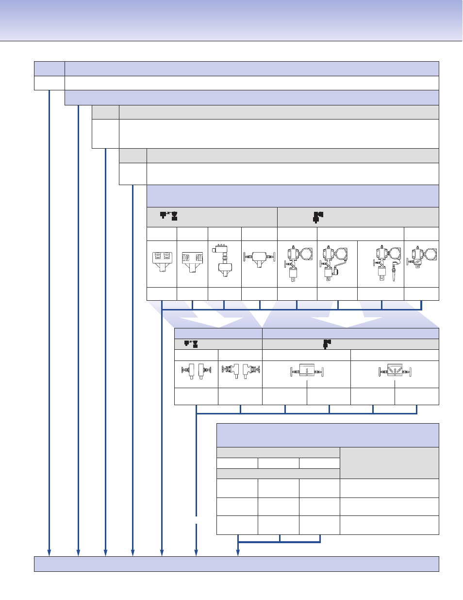
Model
Flanged
V550
Spring Lock
Pipe Size and Schedule or Exact ID and Wall Thickness
Code Sensor Pipe Size Range
05
2” to 6” (50mm to 150mm)
10
6” to 42” (150mm to 1050mm)
15
12” to 60” (300mm to 1500mm)
Code Pipe Orientation
H
Horizontal
V
Vertical
Instrument Connections
(Select Remote or Direct Mount)
(Transmitter sold separately)
Remote Mount Transmitter
Direct Mount Transmitter
(1/2” NPT)
(Flanged 450°F/232°C Max.)†
Parallel
Regular
RTD
*
Valve
Transmount
Mass Transmount
*
Manifold
P
R
D
T
F
G
E
M
V550
8”sch 40
10
H
R
C2NC
F615C
Typical Model Number
Ordering Information
Mounting Assembly — Select Material & Rating
(Includes SS sensor flange, WN flange, weld coupling,
spiral-wound gasket, studs & nuts)
Sensor
(Flange Size)
05 (1”)
10 (1-1/2”)
15 (2”)
Mating Flange Material
Code
& ANSI Class
F415C
F615C
F815C
CS
150#
F415S
F615S
F815S
SS
150#
F430C
F630C
F830C
CS
300#
F430S
F630S
F830S
SS
300#
F460C
F660C
F860C
CS
600#
F460S
F660S
F860S
SS
600#
Optional
Instrument Valves
(Opt.)
Manifolds
(Optional)
Remote Mount
Direct Mount
Needle
Gate
3-Valve
5-Valve
C2NC (CS)
C2GC (CS)
F3SC (CS)
F3HC (CS)
F5SC (CS)
F5HC(CS)
C2NS (SS)
C2GS (SS)
F3SS (SS)
F3HS (SS)
F5SS (SS)
F5HS (SS)
1/2” NPT
Soft Seat
Hard Seat
Soft Seat
Hard Seat
1/2” NPT
Explsn. Proof
Remote
RTD
Integral
RTD
Integral
Integral
*
For high pressure (>500psig) or high temperature (>500°F), remote mount RTD in a thermowell is preferred.
† Assuming adequate heat dissipation for transmitter.