Verabar, Hot tap models, Flow calculation – Veris Verabar V450 Spec Sheet User Manual
Page 2: Select model from page 3, Pipe or duct orientation, Enter flow conditions, V450 low pressure, Model v450
Vera
bar
®
Vera
bar
Flow Calculation
Program
Flow Calculation
Program
5.
Flow Calculation
All Verabar applications require a flow calculation to verify
the DP, pressure and temperature limits, structural limits
and to size the transmitter. The Veracalc PC Program
is for use by representatives and end users. It is easy
to operate and includes steam tables.
Verabar
®
Hot Tap Models
4.
Select Model from Page 3
Use the Ordering Information table on Page 3 to determine your
model number.
Short
Straight Run
Consult Factory
(V) Vertical
(H) Horizontal
Pipe Size _____ Sch _____
Pipe ID _____ and
Wall _____ Pipe Mat’l _____
Wall
Height (H) _____
Width (W) _____
Wall _____
Duct Mat’l _____
Dimension
Verabar spans
(H) or (W)
Fluid Name:
Maximum
Normal
Minimum
Units
Flow Rate
All
Temperature @ Flow
Fluids
Pressure @ Flow
Gas
Specific Gravity, or
Molecular Weight
Liquid
Specific Gravity
Steam
Veracalc Program can calculate Density from Temperature and Pressure
ID
W
H
2.
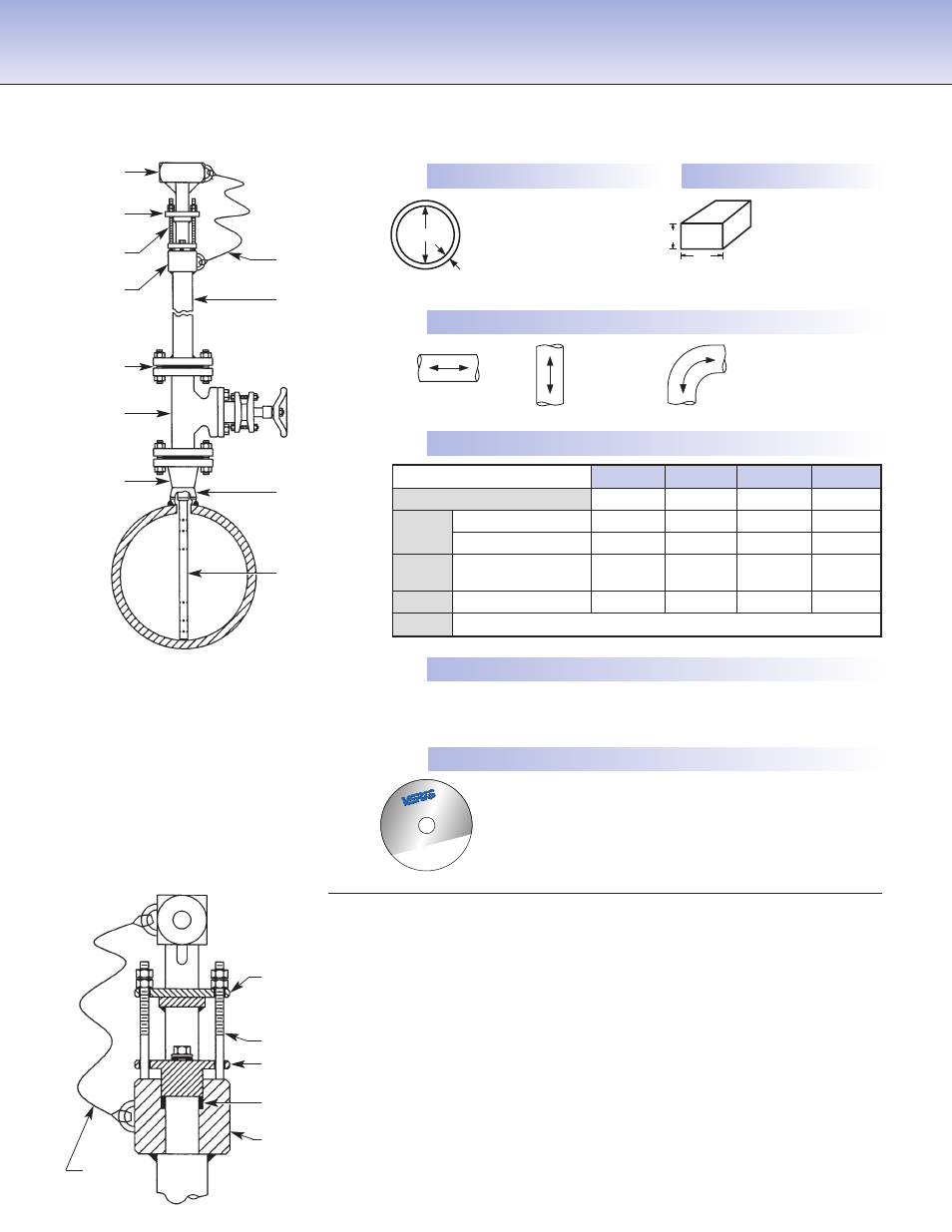
Pipe or Duct Orientation
3.
Enter Flow Conditions
1.
Enter Pipe Dimensions or Duct Dimensions
Furnish the following information:
Retaining Hardware
• Eliminates drive rods
• Safety cable limits retraction length to ensure proper sealing
of packing gland
• Retaining ring loads sensor to opposite pipe wall
V450 Low Pressure
Instrument
head (SS)
Access valve
flange (CS)
(SS opt)
Retaining
ring (SS)
Packing
gland (SS)
Studs & nuts
(SS)
Retaining ring
(SS)
Access
nipple (SS)
Follower (SS)
Weld coupling
(CS) (SS-opt)
Spiral-wound
gasket (2)
Sensor (316SS)
Safety
cable (SS)
Safety
cable (SS)
Safety studs (SS)
Packing gland
(SS)
Model V450
Graphite packing
Weld neck
flange (CS)
(SS opt)