Veris Verabar V500_V510 Installation Instructions User Manual
Page 3
5.2
Weld Mounting Flange to Pipe
•
Loosely bolt together (hand tight) the sensor,
gasket and mounting flange. Insert the assembly
into the pipe. Align the head of the sensor so that
the arrow labeled “flow” on the head is in the
direction of the flow to within 3°. The contour of
the weld coupling should match the contour of the
pipe. Check that the bottom of the weld coupling
is in contact with the pipe wall.
•
Using the appropriate weld gap (1/16” [1.5mm]
typical), tack weld the mounting flange into
position (Figure 3).
Figure 3. Weld Gap
•
Note the flange orientation per Figure 4. The bolt
holes on the flange should straddle the centerline
of the pipe (2-holing pattern). For V510 models,
slide the opposite end weld coupling over the tip of
the sensor and tack weld into position.
•
Remove the sensor and finish welding the weld
coupling(s) per applicable piping codes. For V510
models, weld the weld coupling and weld cap into
position.
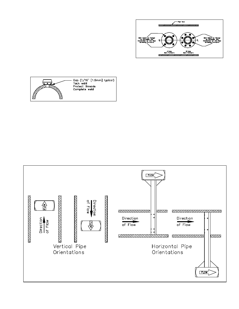
Figure 4. Flange Orientation
5.3
Insert Sensor
Install the sensor with the gasket between the flanges
such that the flow arrow on the head of the sensor is in
the direction of the flow (Figure 5). The nuts should be
tightened until the gasket is completely crushed (the
gasket thickness should be approximately 1/8” [3mm]).
5.4
Insert Instrument Valves or Manifold
5.4.1 Valves
If the Verabar does not have a valve head, install
instrument valves using proper thread sealant. Be sure
instrument shut-off valves are installed and shut prior to
repressurizing the pipe.
5.4.2 Manifold
If the Verabar has a direct or integral manifold, be sure
the high and low pressure block valves are shut off prior
to repressurizing the pipe.
Figure 5. Orientation of Flow Arrow