Periodic maintenance, Sensor removal procedure – Veris Verabar V400D Installation Instructions User Manual
Page 4
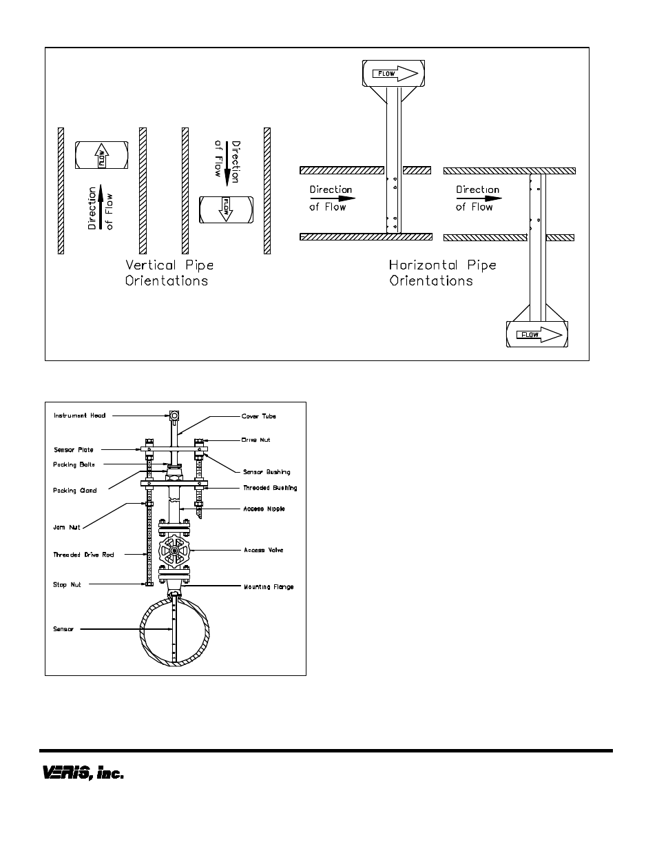
Figure 7. Orientation of Flow Arrow
The Verabar is now properly installed (Figure 8).
Figure 8. Installed V400 (Double)
Periodic Maintenance
The assembly should be periodically checked. Verify
that no leaks are present. The jam nuts and packing
bolts should be tight.
Sensor Removal Procedure
•
Shut off instrument valves.
•
Reduce flow rate to below the maximum insertion
withdrawn DP/flow limit stated on the Verabar tag.
•
Loosen jam nuts.
•
Using the drive nuts, retract the sensor until the
stop nuts and jam nuts are pressing against the
threaded bushings. The drive nuts should be
alternately loosened approximately 1/8” (3mm) at a
time. This will prevent excess bowing of the cover
tube and drive rods.
•
Completely shut off the access valve. Slowly
crack open one of the Verabar instrument valves
and bleed off any remaining pressure contained in
the access nipple. The sensor assembly can now
be removed.
6315 Monarch Park Place
•
Niwot, CO 80503 USA
•
Phone: (303) 652-8550
IO
-400D VWI-CS-028 REV B (6/08)
Fax: (303) 652-8552
•
Email: [email protected]
•
Website: www.veris-inc.com
Printed in USA