Veris Verabar V200D Installation Instructions User Manual
Page 4
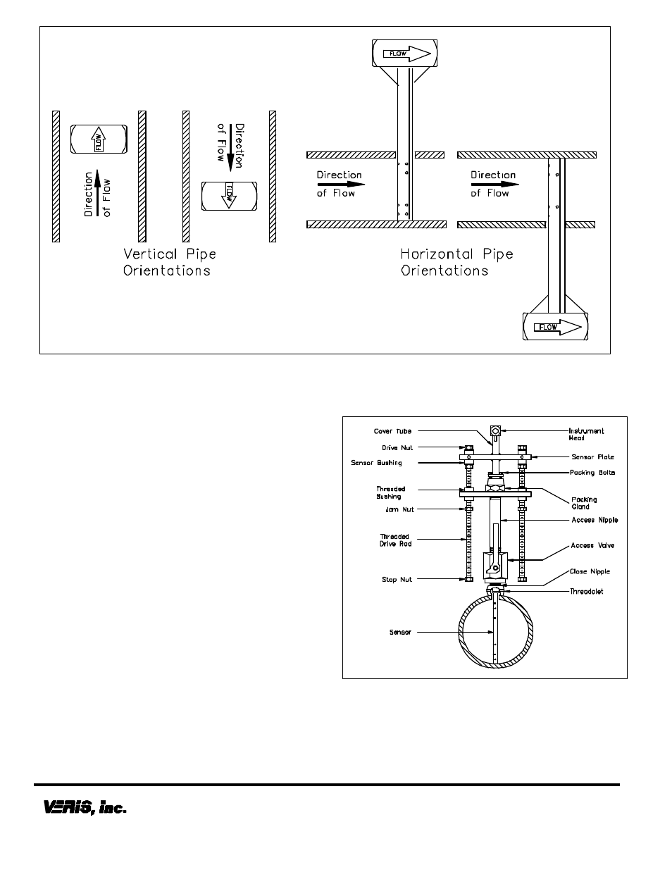
Figure 6. Orientation of Flow Arrow
•
The tip of the sensor should completely bottom on
the opposite end of the pipe. Continue to insert
the sensor until firm resistance is met. This will
occur when the sensor plate is approximately 2”
(51mm) from the top of the packing gland.
•
Thread the jam nuts toward the threaded bushings.
The jam nuts should press tightly against the
threaded bushings. This will lock the drive rods in
place and maintain the sensor position in the pipe.
Periodic Maintenance
The assembly should be periodically checked. Verify
that no leaks are present. The jam nut and packing bolts
should be tight.
Sensor Removal Procedure
•
Shut off instrument valves.
•
Reduce flow rate to below the maximum insertion
withdrawn DP/flow limit stated on the Verabar tag.
•
Loosen jam nut. Using the drive nut, retract the
sensor until the stop nut and jam nut are pressing
against the threaded bushing.
•
Completely shut off the access valve. Slowly
crack open one of the Verabar instrument valves
and bleed off any remaining pressure contained in
the access nipple. The sensor assembly can now
be removed.
The Verabar is now properly installed (Figure 7).
Figure 7. Installed V200 (Double)
6315 Monarch Park Place
•
Niwot, CO 80503 USA
•
Phone: (303) 652-8550
IO
-200D VWI-CS-024 REV B (6/08)
Fax: (303) 652-8552
•
Email: [email protected]
•
Website: www.veris-inc.com
Printed in USA