Mains voltage connection diagram – Velleman VMB4RYNO User Manual
Page 9
VMB4RYNO 4-channel relay module user manual - version 1
9
USE
The relay module features 4 non-voltage NO contacts wich allow you to switch mains-voltage (230V) and low-
voltage (12 or 24V) consumers.
The module is integrated into the Velbus system and controlled through the VMB4PD control panel or by means
of pushbuttons connected to a VMB8PB pushbutton interface, VMB6IN or any other relay module.
To interconnect the Velbus modules it is recommended to use a twisted-pair cable (EIB 2x2x0.8mm², UTP
4x2x0.51mm² - CAT5 or equivalent).
Make sure to use a heavy-gauge wire (0.5mm
2
or more) in case of a multiple module connection (>10 modules) or
with log connections (>50m).
Connect the bus to the module (mind the polarity).
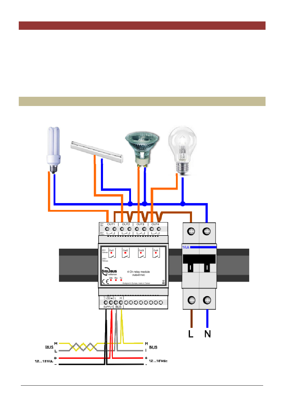
Mains Voltage Connection Diagram
A single-pole load (e.g. lighting) can be connected directly to the output.
- PS1502A (6 pages)
- VMB6PBN (15 pages)
- VTTEST14 (5 pages)
- VMB3PS (10 pages)
- PSSE60 (18 pages)
- VMB8IR (10 pages)
- PSSE24 (4 pages)
- VMBLCDWB (12 pages)
- VMB1TSW (24 pages)
- VL3288 (5 pages)
- PSSMV24 (23 pages)
- VMB4IRT (16 pages)
- VMB7IN (8 pages)
- VMB1USB (6 pages)
- PSI600B (29 pages)
- VL06LA (4 pages)
- PSSEUSB6A (2 pages)
- PS603 (17 pages)
- VMB1TS (43 pages)
- PSSE23 (4 pages)
- VL1212 (29 pages)
- VL7168 (7 pages)
- PSSE45 (19 pages)
- PS925 (13 pages)
- VMB1BL (12 pages)
- VMB1RS (6 pages)
- PSS1320 (11 pages)
- PSSMV8 (20 pages)
- VMB8PB (16 pages)
- VMB4RF (8 pages)
- VMBRSUSB (8 pages)
- PI300BN (33 pages)
- VMBGPTCx (12 pages)
- PSC1350 (2 pages)
- VTTEST15 (7 pages)
- PSSEUSB4 (2 pages)
- VMB4DC (18 pages)
- VMBGP1x (12 pages)
- PSSMV2 (4 pages)
- VMB8PBU (12 pages)
- PSIC75B (18 pages)
- PS12015 (5 pages)
- VMB4TX (1 page)
- VL6278 (12 pages)
- VMB4PD (35 pages)