Soft dB Zen-Ten Spec sheet User Manual
Page 3
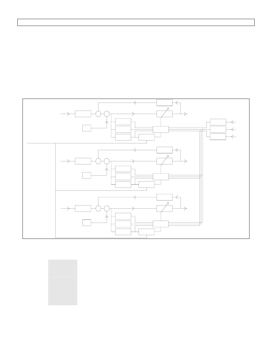
Details of the Control Algorithm Running on the DSP
The X-LMS optimization is done in real time for a selectable sampling frequency up to 78.125 kHz.
In coupled mode, the secondary control cross-paths are taken into account during the LMS optimization.
In non-coupled mode, the control system acts like three separate mono-channel controllers.
The Reference signal Rx(n) can be filtered by an adjustable high-pass to remove the DC component of the
signal.
The Error signals Ex(n) can be filtered by an adjustable high-pass to remove the DC component of the signal.
Adjustable pass-band or low-pass filter on the reference and Error Signals to force the control on a specific
spectral zone.
Normalized adaptation step size Mu
White noise (W.N.) generator can be added to the reference signals for greater control stability.
W1
LMS_1
C1(n)
C1R1
-
R1(n)
C1E3
F_R1
F_E1
E1(n)
+
W.N.
Norm 1
Mu
C1E2
C1E1
C2R2
W2
Norm 2
C2E2
R2(n)
W.N.
F_R2
-
C2E3
C2E1
+
LMS_2
E2(n)
F_E2
C2(n)
E3(n)
F_E3
W3
C3R3
W.N.
R3(n)
F_R3
-
LMS_3
C3E2
C3E3
Norm 3
C3E1
+
C3(n)
Figure 2 Schematic for coupled version of the control algorithm
Note:
Wx
Control filter x
CxEy
Filter of the secondary control path between the control output x
and the error sensor y
CxRx
Filter of the primary control path between the control output x and
the reference sensor y
Norm x
Function for the normalization of the adaptation step. The
normalization is done with the energy of the filtered reference.
LMS_x
Optimization function (LMS) for the control filter x.