Aluminum parabolic louvers, Vd lighting b a sic s, Opvdt series – Oracle Lighting OPVDT-22 User Manual
Page 2: Vd t b as ics, Rp1 ies
50
www.oraclelighting.com • tel: 1-877-375-5555 • FaX: 1-877-375-3333
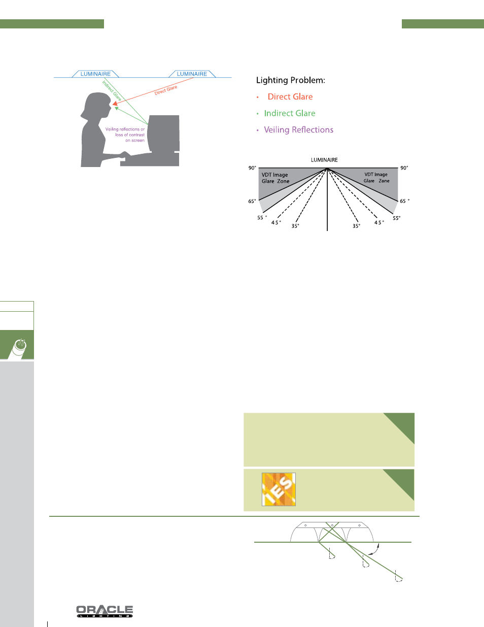
Lighting Solution:
• Select luminaires that minimize intensity in the 55° or 65° to 90°
zone.
• In “vdt normal” spaces with a mix of paper and non-critical
vdt tasks, the ies recommends that the luminous intensity in
the lengthwise, crosswise and 45° vertical planes should not
exceed*:
300 candelas at 65° from vertical
185 candelas at 75° from vertical
60 candelas at 85° or more from vertical
• In “vdt intensive” spaces where the majority of the time is spent
viewing the vdt, the ies recommends that the luminous intensity
in the lengthwise, crosswise, and 45° vertical planes should not
exceed*:
300 candelas at 55° from vertical
220 candelas at 65° from vertical
135 candelas at 75° from vertical
45 candelas at 85° from vertical
• Select luminaires with shielding angles of at least 30° in all direc-
tions.
• Design to a maximum of 50** maintained footcandles on the
horizontal work plane.
• Locate vdt terminals between rows of luminaires when possible.
Other Considerations:
• Windows should be treated with blinds or curtains to eliminateex-
cessive brightness.
• Most vdt terminals may be tilted (up or down) or turned (side to
side) to minimize reflected glare.
• White clothing worn by operator may cause some loss of contrast
on screen.
• Negative contrast monitors (dark detail on a light background)
frequently make reflected glare less noticeable.
• Monitor design (screen curvature or flat screen, screen reflec-
tance properties, etc.) can make significant differences in visual
performance.
• Use of screen filters supplied by manufacturers of visual display
terminals helps to reduce screen glare.
• Partitions may be located as needed to reduce reflections from
windows or luminaires. Source: iesna rp-1 (2004) recommended
practice for lighting offices containing computer visual display
terminals.
*These values are candlepower rather then luminance values as in
previous recommendations.
**Illuminating engineering society of north America (iesna) recom-
mended level.
Louver Iridescence:
• Iridescence Phenomena, present on lighting sheet reflectors, is
caused by the refraction of light by the thin anodic coating that
produces either cancellation or reinforcement of certain wave-
lengths of light. This “rainbow effect” appears primarily as various
shades of green and pink that can change color at different view-
ing angles.
• Iridescence has always been present on lighting sheet reflectors,
but to a very subtle, often un-noticeable degree with the tradi-
tional fluorescent light sources that emitted a broad spectrum of
light. With the introduction of fluorescent light sources that utilize
rare-earth phosphors and emit distinct wavelengths of light, the
phenomena of iridescence has been intensified and has become
an aesthetic problem to the user. It should be recognized that the
presence of iridescence does not detract from the optical perfor-
mance of the lighting sheet reflector.
• Unfortunately, there is currently no quantitative way to measure
iridescence, so we are left with a purely subjective evaluation
of what is objectionable and this can vary from individual to
individual.
• Low iridescence aluminum is recommended for use with T8,
compact fluorescent TT5, and other tri-phosphor lamps.
alUminUm ParaBolic loUVerS
-oPVDt SerieS-
VD
lighting
B
a
Sic
S
illUminating
engineering
SocietY oF north america
ieS recommenDeD
Practice For
lighting oFFiceS
containing
comPUter ViSUal
DiSPlaY terminalS
RP1
The blades of a parabolic louver provide a physical cut-off
in the same way as in an “egg-crate” louver, however, a
parabolic louver with a specular silver finish reflects all
light from its curved blades at an angle equal to or less
than the louver cut-off angle
V
D
t
B
as
ics
OPTICAL CUT-OFF ANGLE
LAMP CUT-OFF ANGLE
LOUVER CUT-OFF ANGLE
SHIELDED ZONE
CEILING MOUNT
RP1
IES
T8/T5
OPVDT