Load cell connections, Unpacking, Installation – Ohaus PL150 Scale Bases User Manual
Page 4: Load cell cable connections, Connection to ohaus i10 indicator
4
UNPACKING
UNPACKING
UNPACKING
UNPACKING
UNPACKING
Carefully unpack and remove the Scale Base from the packing material.
NOTE
NOTE
NOTE
NOTE
NOTE: It is recommended that you save the packing material. It will be of value
when storing and/or transporting the Scale Base.
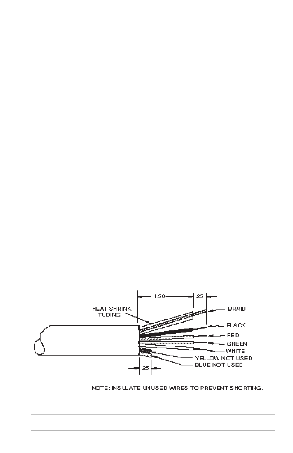
Load Cell Cable Wire Preparation
INSTALLATION
Load Cell Cable Connections
Load Cell Cable Connections
Load Cell Cable Connections
Load Cell Cable Connections
Load Cell Cable Connections
Connect the load cell cable of the Scale Base to the indicator as follows:
NOTE:
These steps may be omitted if the Scale Base was purchased with the I5S as a
Model BxxxS Bench Scale.
Connection to Ohaus Model I10 Indicator
Connection to Ohaus Model I10 Indicator
Connection to Ohaus Model I10 Indicator
Connection to Ohaus Model I10 Indicator
Connection to Ohaus Model I10 Indicator
Plug the load cell cable connector directly into the receptacle at the rear of the
indicator.
Connection to Ohaus Models I5S, I20W and I150 Indicators
Connection to Ohaus Models I5S, I20W and I150 Indicators
Connection to Ohaus Models I5S, I20W and I150 Indicators
Connection to Ohaus Models I5S, I20W and I150 Indicators
Connection to Ohaus Models I5S, I20W and I150 Indicators
The load cell cable must be hard wired to the terminal block of the indicator. This
will require removal of the load cell cable connector and preparation of the load cell
wires as illustrated below.