EVS GX Version 1.5 - September 2011 User’s Manual User Manual
Page 22
Issue 1.5.A
GX server – Version 1.5 – Users Manual
EVS Broadcast Equipment – September 2011
14
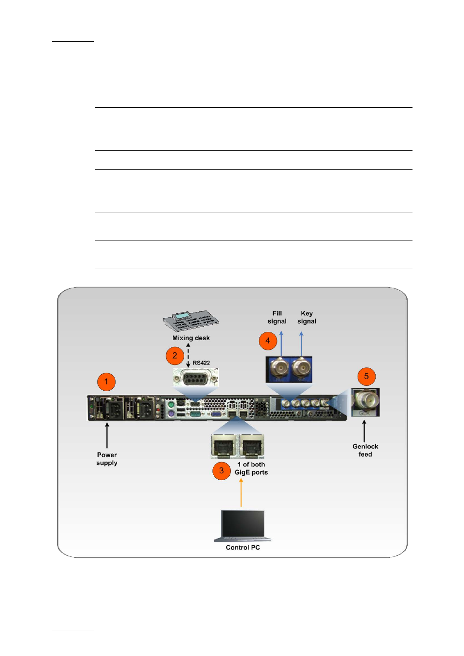
The schema below shows how the GX server needs to be cabled before switching
it on. The table hereafter briefly describes the connections highlighted on the
schema:
#
Description
1.
Connect the power supply to mains.
Connect the second power supply to allow automatic power switching in case
of failure.
2.
Connect the VDCP client to the RS 422 port on the GX server.
3.
Connect the GX server to the local area network via one of the GigE ports.
This will allow users to connect remotely to the GX server via the GX web
interface.
4.
Connect the KEY and FILL connectors to the video equipment that will
perform the keying of the GX outputs.
5.
Connect the Genlock feed to the GLK connector to make sure the video
signals from the GX server are synchronized in your setup.
The mouse, keyboard and VGA connectors at the back of the server also allow
users to directly connect to the server, mainly to perform tests and checks.
- XFReader Version 2.6 - October 2013 User Manual (44 pages)
- Xfile Version 2.14 - January 2011 User Manual (190 pages)
- MulticamLSM Version 9.00 - March 2008 User's Manual (201 pages)
- XstoreSE (4 pages)
- XEDIO Importer Version 3.1 - January 2011 User Manual (34 pages)
- Xfile Version 1.01 - December 2006 User Manual (42 pages)
- XTract Version 1.01 - January 2011 User Manual (15 pages)
- MulticamLSM Version 8.03 - Dec 2006 User's Manual (156 pages)
- IPDirector Version 6.2 - June 2013 CHANNEL EXPLORER User Manual (48 pages)
- XS Version 11.02 - July 2013 Configuration Manual (204 pages)
- GX Version 1.00 - February 2011 User’s Manual (66 pages)
- LSM Connect (32 pages)
- MulticamLSM Version 10.01 - July 2009 Operating Manual (185 pages)
- XStoreSAN (4 pages)
- XTract Installation Note (1 page)
- MulticamLSM Version 10.03 - July 2010 Configuration Manual (97 pages)
- XTAccess Version 1.18 - July 2012 User Manual (109 pages)
- XEDIO Manager Version 3.1 - January 2011 User Manual (134 pages)
- EpsioAir (2 pages)
- XSense Version 10.04 - January 2011 Operating Manual (164 pages)
- MultiReview (2 pages)
- XEDIO Media Cleaner Version 3.1 - January 2011 User Manual (16 pages)
- XEDIO Media Cleaner Version 3.1 - January 2011 User Manual (18 pages)
- XEDIO Media Cleaner Version 4.1 - December 2011 User Manual (17 pages)
- XEDIO Playout Organizer Version 4.35 - August 2013 User Manual (36 pages)
- IPDirector Version 6.0 - November 2012 Part 2 User's Manual (92 pages)
- IPWeb Version 1.0 - June 2013 User Manual (76 pages)
- XEDIO Ingest Organizer Version 3.1 - January 2011 User Manual (22 pages)
- XTnano Version 11.02 - July 2013 Operation Manual (102 pages)
- Xfile Version 2.13 - July 2010 User Manual (192 pages)
- IP2Archive Version 1.2 - October 2012 User Manual (30 pages)
- XEDIO Importer Version 4.35 - August 2013 User Manual (38 pages)
- XTract Version 1.00 - May 2010 User Manual (16 pages)
- XEDIO Browse Version 3.1 - January 2011 User Manual (38 pages)
- EPSIO Version 1.63 - May 2011 User's Manual (73 pages)
- IPDirector Version 6.0 - November 2012 Part 10 User's Manual (30 pages)
- IPDirector Version 6.2 - June 2013 IPLOGGER User Manual (74 pages)
- IPDirector Version 5.8 - July 2010 Part 7 User's Manual (229 pages)
- XFLY Streamer Version 1.02 - April 2013 User Manual (25 pages)
- OpenCube MXFTK Version 2.6 - October 2013 User Manual (42 pages)
- IPDirector Version 4.3 - October 2007 Part 3 User's Manual (204 pages)
- IP2Archive Deep Archive Sync Version 1.1 - October 2012 User Manual (66 pages)
- XEDIO Playout Organizer Version 3.1 - January 2011 User Manual (29 pages)
- MulticamLSM Version 10.04 - January 2011 Configuration Manual (98 pages)
- XTAccess Version 1.19 - November 2012 User Manual (112 pages)