Safety cable installation, Фф фф ф фф ф, Safety cable installation fig. 2 fig. 1 – Blue Ox BX7322 User Manual
Page 3: Fig. 4, Fig. 3 coupler fit adjustment, 16" to 34" between centerlines
© 2003, 04, 07, 08, 09
Blue Ox Division, Automatic Equipment Mfg. Co. • One Mill Road, Industrial Park
Pender, Nebraska 68047 • Phone 402-385-3051 • Fax 402-385-3360 • www.blueox.us
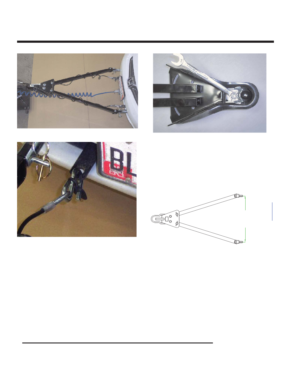
16" TO 34"
BETWEEN
CENTERLINES
REFER TO #4 ON PAGE #2 FOR
INFORMATION TO TIGHTEN 4
COUPLER BOLTS
F
c
reated
w
ith
pdfF
a
ctory
P
ro tri
a
l
v
ersi
on
w
w
w
factory
.com
1. Arrange the cables in an “X” pattern below the tow bar and make one or two wraps around the tow bar legs
if needed. (See Figure 1)
2. Solidly connect the cables to the chassis of both the towing and the towed vehicles or baseplate convenience
links if available. Insure the rubber keepers are in place. (See Figure 2) NOTE: Permanent chains will need
to be installed between the convenience links and the towed vehicle’s frame if the links are to be used.
3. Do not allow too much or too little slack in the cables.
4. If BX88196 cables are not used, be sure each cable or chain used has at least the load rating of the cou-
pler.
SAFETY CABLE INSTALLATION
Fig. 2
Fig. 1
SAFETY CABLE INSTALLATION
Page 3 of 5
292-1263 Rev. H
8/19/09
Fig. 4
1. Using a 3/4" socket or wrench, tighten or loosen
the nut until fi rm contact between coupler and
ball is established. Perform adjustment when
the coupler is in locked position. (Note: Bottom
of coupler is shown above in Fig. 3)
2. Check ball to housing tension periodically and
tighten if needed.
Fig. 3
COUPLER FIT ADJUSTMENT
Ф
Ф ФФ
Ф
ФФ
Ф