Dimensions in inches – American Magnetics Current Leads for Cryogenic Systems Brochure User Manual
Page 3
Model Number
L-50
L-75
L-100
L-150
L-200
L-250
L-500
L-1000
L-2000
L-3000
L-5000
L-10000
Amperes
50
75
100
150
200
250
500
1000
2000
3000
5000
10000
Approx. Helium
Consumption,
0.16
0.24
0.32
0.48
0.64
0.8
1.6
3.2
6.4
9.6
16.0
32.0
Liters/Hr.
(pair of leads)
Type
A
A
A
A
A
A
A
B
B
B
B
B
A
1/4
1/4
1/4
1/4
3/8
3/8
1/2
1/2
1/2
1/2
3/4
3/4
B
1-1/2
1-1/2
1-1/2
1-1/2
2
2
3
3
3
3-3/4
4-1/2
7
C
1
1
1
1
1-1/4
1-1/4
1-1/2
2
2-1/2
3
3
3-1/2
D
--
--
--
--
--
--
--
1
1
1-1/2
1-1/2
2
E
9/32
9/32
9/32
9/32
9/32
9/32
9/16
9/32
7/16
7/16
7/16
7/16
F
3/8
3/8
3/8
3/8
1/2
1/2
3/4
3/4
3/4
1
1
1 & 3
G
3/8
3/8
3/8
3/8
1/2
1/2
1/2
7/8
1-1/8
1-1/4
1-1/2
2-1/2
H
1/4
1/4
1/4
1/4
3/8
3/8
1/2
1/2
3/4
1
1
1-3/4
I
--
--
--
--
--
--
--
2-1/4
2-1/2
2-5/8
3
3-3/4
J
--
--
--
--
--
--
--
1-3/4
2
2-1/8
2-1/4
3-1/4
K
1/4 NPT 1/4 NPT 1/4 NPT 1/4 NPT 3/8 NPT 3/8 NPT 1/2 NPT
1
1-1/4
1-3/8
1-5/8
--
L
7/8
7/8
7/8
7/8
1
1
1-3/16
5/8
5/8
5/8
5/8
3/8
M
9/16
9/16
9/16
9/16
9/16
9/16
3/4
3/8
3/8
3/8
3/8
--
N
--
--
--
--
--
--
--
9/32
9/32
9/32
9/32
9/32
O
1/4
1/4
1/4
1/4
3/8
3/8
1/2
3/4
1
1-1/8
1-3/8
2-1/8
R
--
--
--
--
0.201
0.201
0.201
9/32
13/32
17/32
17/32
3/8
S
1
1
1
1
1
1
1
1-1/2
1-1/2
1-1/2
1-1/2
4
T
1/16
1/16
1/16
1/16
1/8
1/8
1/8
1/4
1/4
1/4
1/4
3/8
U
--
--
--
--
1/4
1/4
1/4
1/2
1/2
1/2
1/2
1 & 2-1/2
V
16-5/8
16-5/8
16-5/8
16-5/8
16-5/8
16-5/8
17-1/2
19-1/2
19-1/2
19-1/2
19-1/2
24
W
Adjust.
Adjust.
Adjust.
Adjust.
Adjust.
Adjust. Adjust.
1-1/2
2
2
2
4
X
1/4
1/4
1/4
1/4
3/8
3/8
1/2
3/4
1
1-1/8
1-3/8
2-1/8
Y
5/8
5/8
5/8
5/8
1/2
1/2
1/2
3/4
1
1
1
1
DIMENSIONS IN INCHES
VOLTAGE ISOLATION
There are at least three areas of concern when
dealing with proper voltage isolation of current leads:
• Isolation from the cryostat
• Isolation from other leads or structures internal to
the cryostat
• Isolation from any helium gas recovery system.
AMI has the capability to address all of these issues.
Fiberglass is commonly used on the lead shaft and
warm end tabs to isolate the leads from the cryostat
and other leads.
Flanged ceramic-to-metal type isolators are often used
in-line on the gas collection system and are available
for most sizes of current leads.
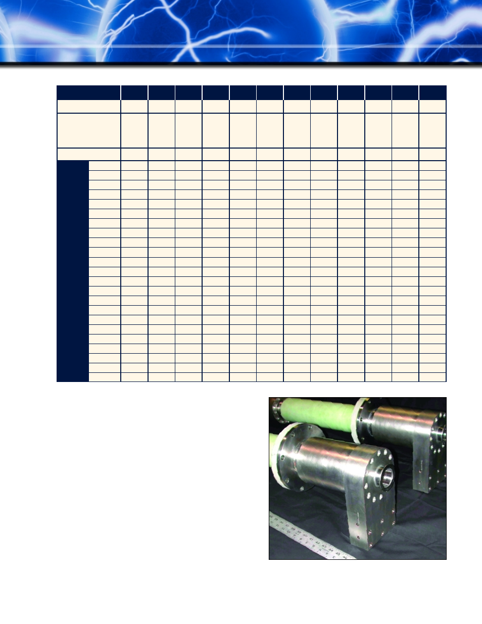
High current leads pictured with voltage isolation flanges
and tubes installed