American Magnetics AMI Liquid Helium Level Sensors User Manual
Page 4
Rev. 1
4
AMI
EXCELLENCE IN MAGNETICS AND CRYOGENICS
liquid level is saved and displayed. The whole process is repeated at intervals selected
by the customer. The liquid losses increase as the sample frequency increases.
The losses for worst case conditions can be estimated if all the parameters are known.
Parameters are defined as follows:
Q
h
= Power produced in watts by the heater at the top.
Q
v
= Power produced in watts during the growth of resistive zone towards liquid
level.
Q
s
= Power produced in watts after static conditions are reached, i.e. after the
resistive zone reaches the liquid surface.
I = Sensor current (0.075 amperes).
R
h
= Heater resistance (approximately 5 ohms).
R
s
= Normal state resistance/length of NbTi filament (approximately 4.55 ohm/
cm @ 20K).
v = velocity of propagation of resistive zone (approximately 20 cm/second @ 75
milli-ampere sensor current).
L
G
= length in cm of sensor active region NOT submerged in liquid helium.
t = amount of time the current is on in seconds.
t
0
= time at which normal zone starts propagating in seconds.
t
1
= time at which resistive zone stops at liquid level in seconds.
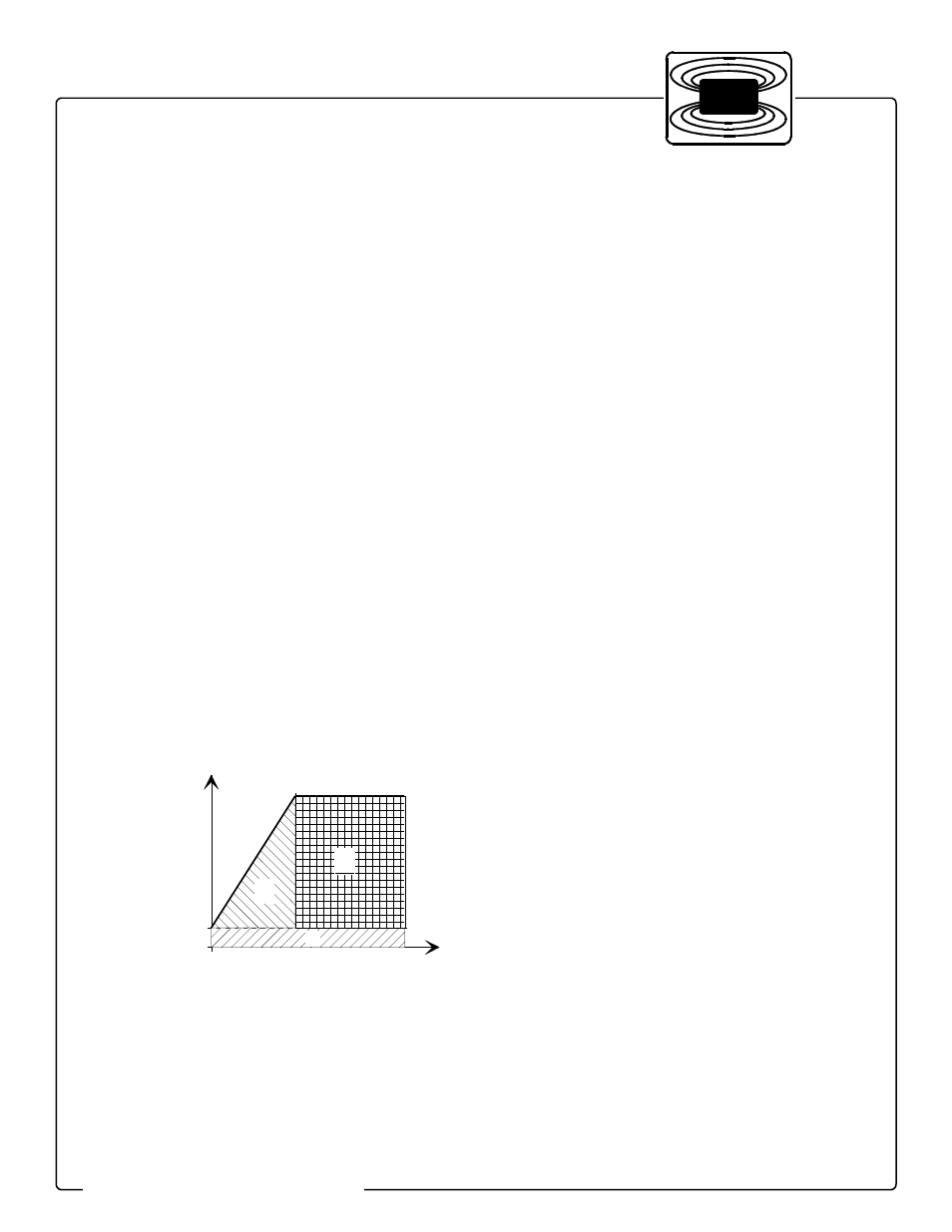
There are three regions where heat is produced:
Region I. The heater region
Heat is produced as long as the current is on.
Q
h
= I
2
• R
h
• t
I
II
III
Po
w
e
r
time