Bosch GWS 24-180 H Professional User Manual
Page 18
English | 19
Bosch Power Tools
1 609 92A 0B8 | (5.8.13)
6 Locking screw for protection guard
7 Mounting flange with O-ring
8 Grinding wheel*
9 Clamping nut
10 Two-pin spanner for clamping nut*
11 Quick-clamping nut
*
12 Carbide grinding head*
13 Protection guard for cutting*
14 Cutting disc*
15 Protection guard for for grinding cup*
16 Grinding cup*
17 Two-pin spanner, offset, for grinding cup*
18 Hand guard*
19 Spacer discs*
20 Rubber sanding plate*
21 Sanding sheet*
22 Round nut*
23 Cup brush*
24 Cutting guide with dust extraction protection guard *
25 Diamond cutting disc*
26 Handle (insulated gripping surface)
*Accessories shown or described are not part of the standard de-
livery scope of the product. A complete overview of accessories
can be found in our accessories program.
Noise/Vibration Information
Measured sound values determined according to EN 60745.
Typically the A-weighted noise levels of the product are:
Sound pressure level 93 dB(A); Sound power level
104 dB(A). Uncertainty K =3 dB.
Wear hearing protection!
Vibration total values a
h
(triax vector sum) and uncertainty K
determined according to EN 60745:
Surface grinding: a
h
=7.5 m/s
2
, K=1.5 m/s
2
,
Disk sanding: a
h
=4.5 m/s
2
, K=1.5 m/s
2
.
The vibration emission level given in this information sheet
has been measured in accordance with a standardised test
given in EN 60745 and may be used to compare one tool with
another. It may be used for a preliminary assessment of expo-
sure.
The declared vibration emission level represents the main ap-
plications of the tool. However if the tool is used for different
applications, with different accessories or poorly maintained,
the vibration emission may differ. This may significantly in-
crease the exposure level over the total working period.
An estimation of the level of exposure to vibration should also
take into account the times when the tool is switched off or
when it is running but not actually doing the job. This may sig-
nificantly reduce the exposure level over the total working pe-
riod.
Identify additional safety measures to protect the operator
from the effects of vibration such as: maintain the tool and the
accessories, keep hands warm, organise work patterns.
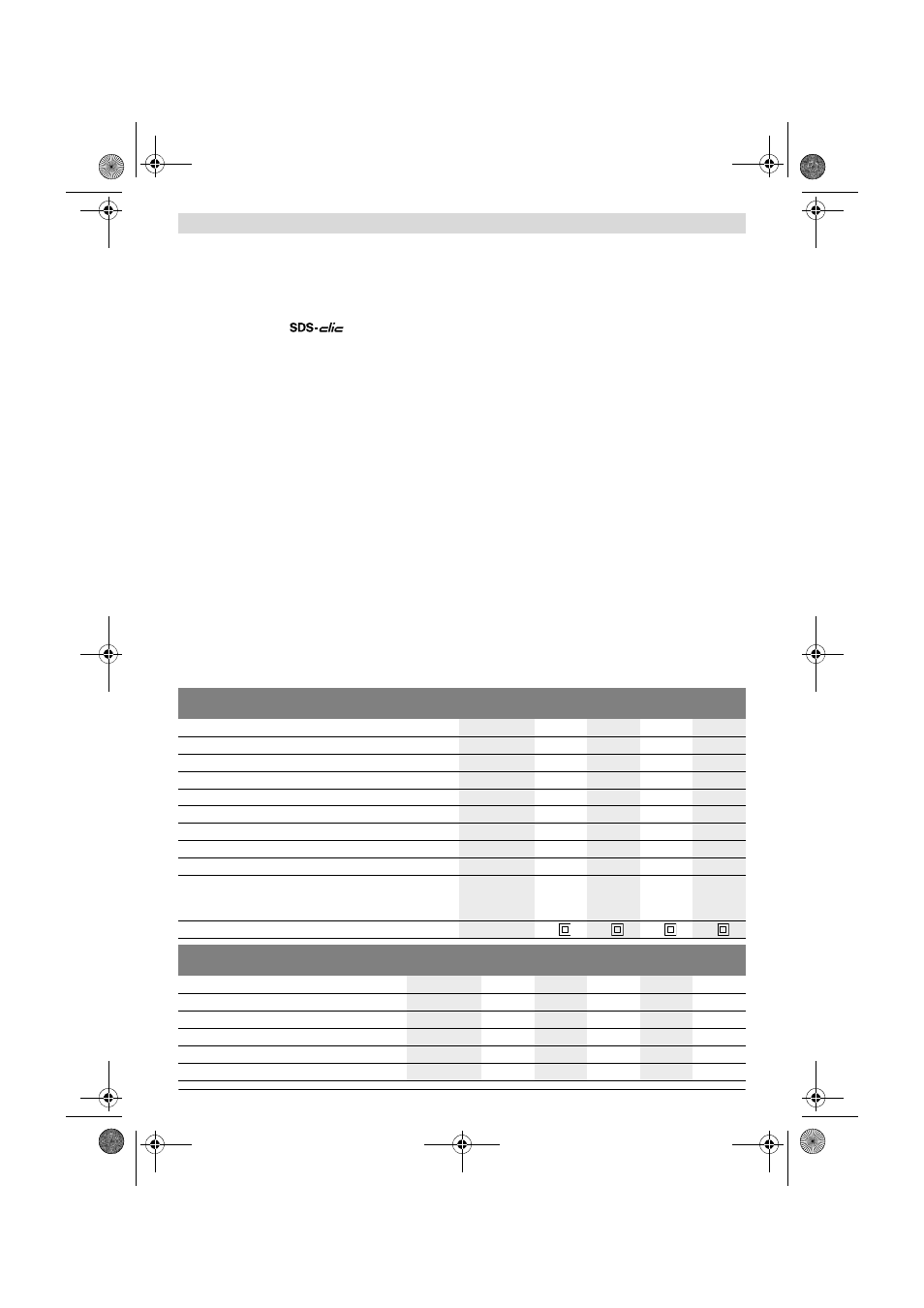
Technical Data
Angle Grinder
GWS ...
22-180
H
22-180
JH
22-230
H
22-230
JH
Article number
3 601 ...
H81 L..
H81 M..
H82 L..
H82 M..
Rated power input
W
2200
2200
2200
2200
Output power
W
1500
1500
1500
1500
Rated speed
min
-1
8500
8500
6500
6500
Grinding disc diameter, max.
mm
180
180
230
230
Thread of grinder spindle
M 14
M 14
M 14
M 14
Thread length (max.) of grinder spindle
mm
25
25
25
25
Restarting Protection
–
–
Reduced starting current
–
–
Weight according to EPTA-Procedure 01/2003
– with vibration-damping auxiliary handle
– with standard-auxiliary handle
kg
kg
5.1
5.0
5.1
5.0
5.3
5.2
5.3
5.2
Protection class
/
II
/
II
/
II
/
II
Angle Grinder
GWS ...
24-180
JH
24-230
H
24-230
JH
26-180
JH
26-230
JH
Article number
3 601 ...
H83 M..
H84 L..
H84 M..
H55 M..
H56 M..
Rated power input
W
2400
2400
2400
2600
2600
Output power
W
1600
1600
1600
1700
1700
Rated speed
min
-1
8500
6500
6500
8500
6500
Grinding disc diameter, max.
mm
180
230
230
180
230
Thread of grinder spindle
M 14
M 14
M 14
M 14
M 14
OBJ_BUCH-777-009.book Page 19 Monday, August 5, 2013 11:15 AM