Pc_to_rdr_setparameters – ACS ACR33U-A1 SmartDuo Smart Card Reader User Manual
Page 17
ACR33U-A1 – Reference Manual
Version 1.02
www.acs.com.hk
Page 17 of 60
8.1.6.
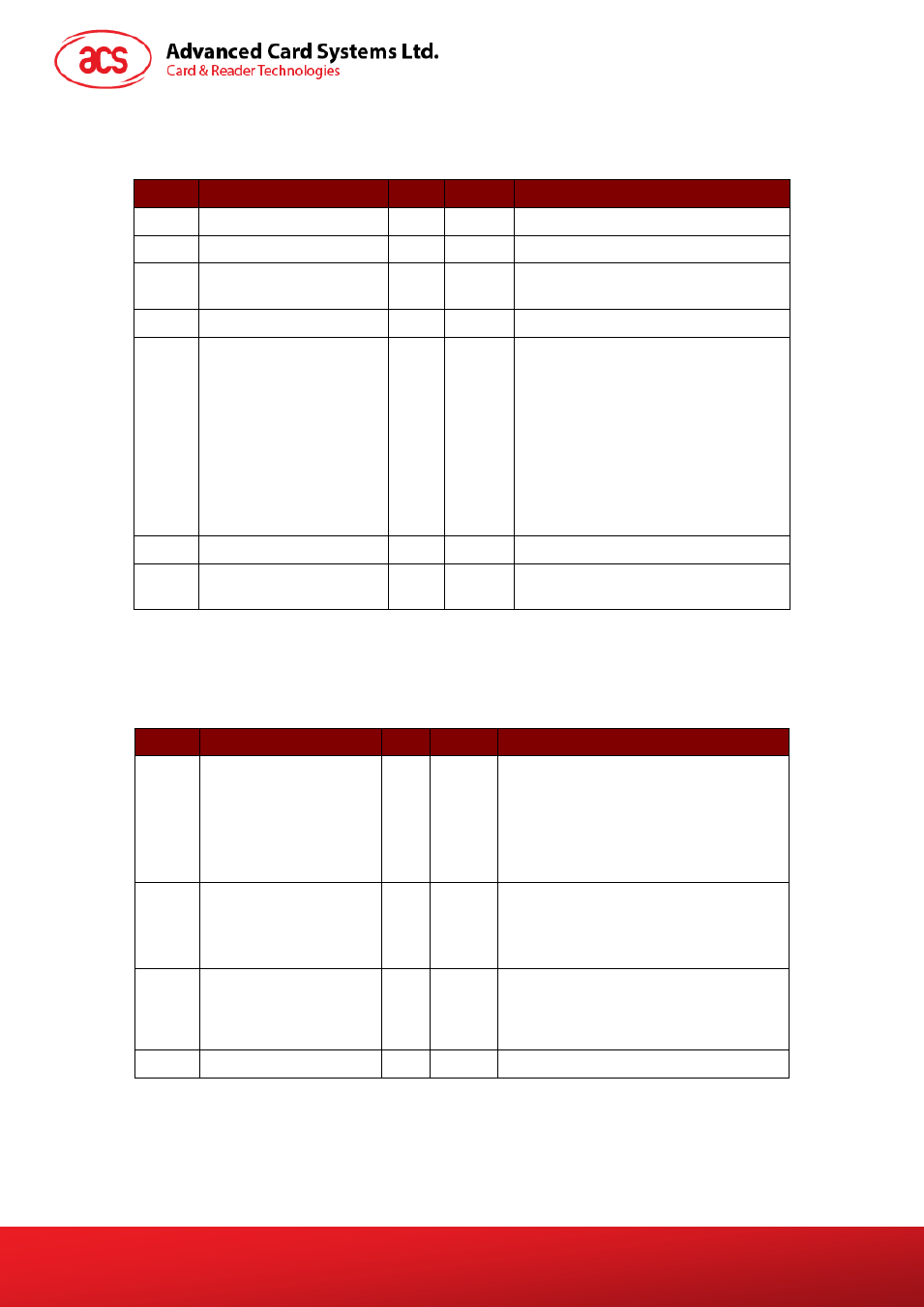
PC_to_RDR_SetParameters
Sets slot parameters.
Offset
Field
Size
Value Description
0
bMessageType
1
61h
-
1
dwLength
4
-
Size of extra bytes of this message
5
bSlot
1
00-05h Identifies the slot number for this
command
6
bSeq
1
00-FFh Sequence number for command
7
bProtocolNum
1
00h,
01h
Specifies what protocol data structure
follows.
00h = Structure for protocol T=0
01h = Structure for protocol T=1
The following values are reserved for
future use:
80h = Structure for 2-wire protocol
81h = Structure for 3-wire protocol
82h = Structure for I2C protocol
8
abRFU
2
-
Reserved for future use
10
abProtocolDataStructure Byte
array
-
Protocol Data Structure
The response to this message is the RDR_to_PC_Parameters message.
Protocol Data Structure for Protocol T=0 (dwLength=00000005h)
Offset
Field
Size Value Description
10
bmFindexDindex
1
-
B7-4 – FI – Index into the Table 7 in
ISO/IEC 7816-3:1997 selecting a clock
rate conversion factor
B3-0 – DI - Index into the Table 8 in
ISO/IEC 7816-3:1997 selecting a baud
rate conversion factor
11
bmTCCKST0
1
-
B0 – 0b, B7-2 – 000000b
B1 – Convention used (b1=0 for direct,
b1=1 for inverse) Note: The CCID
ignores this bit.
12
bGuardTimeT0
1
00-FFh
Extra guard time between two
characters. Add 0 to 254etu to the
normal guard time of 12etu. FFh is the
same as 00h.
13
bWaitingIntegerT0
1
00-FFh WI for T=0 used to define WWT