Mechanical, A. chassis location, B. chassis installation – ACR&Artex ELT to Nav Interface Boeing User Manual
Page 43
25-69-11
Page 43 of 58
JUL 28/11
ACR ELECTRONICS, INC / ARTEX PRODUCTS
ABBREVIATED COMPONENT MAINTENANCE MANUAL
-B (453-6501)
TASK 25-69-11-450-802
2. Mechanical
SUBTASK 25-69-11-450-001
A. Chassis Location
CAUTION:
AVOID LOCATING THE ELT/NAV INTERFACE -B WHERE IT MAY BE SUBJECTED TO
UNPROTECTED EXPOSURE TO HARSH CHEMICAL FLUIDS, SUCH AS DEICING
COMPOUNDS. THESE TYPES OF CHEMICALS MAY CAUSE DAMAGE TO FASTENERS AND
ELECTRICAL COMPONENTS, AS WELL AS ELECTRICAL CONNECTOR CORROSION.
(1)
Mount the ELT/NAV Interface -B within 2 feet (610 mm) of the ELT, such that the interface
harness does not exceed 3 feet (914 mm) including strain relief.
(2)
The ELT/NAV Interface -B chassis and ELT are mounted to the same support structure in most
installations.
SUBTASK 25-69-11-450-002
B. Chassis Installation
(1)
Coordinate ELT/NAV Interface -B chassis installation with ELT installation whenever possible.
If the ELT/NAV Interface -B is an add-on to an existing ELT installation, extend/modify the
existing ELT support structure to accommodate the ELT/NAV Interface -B.
(2)
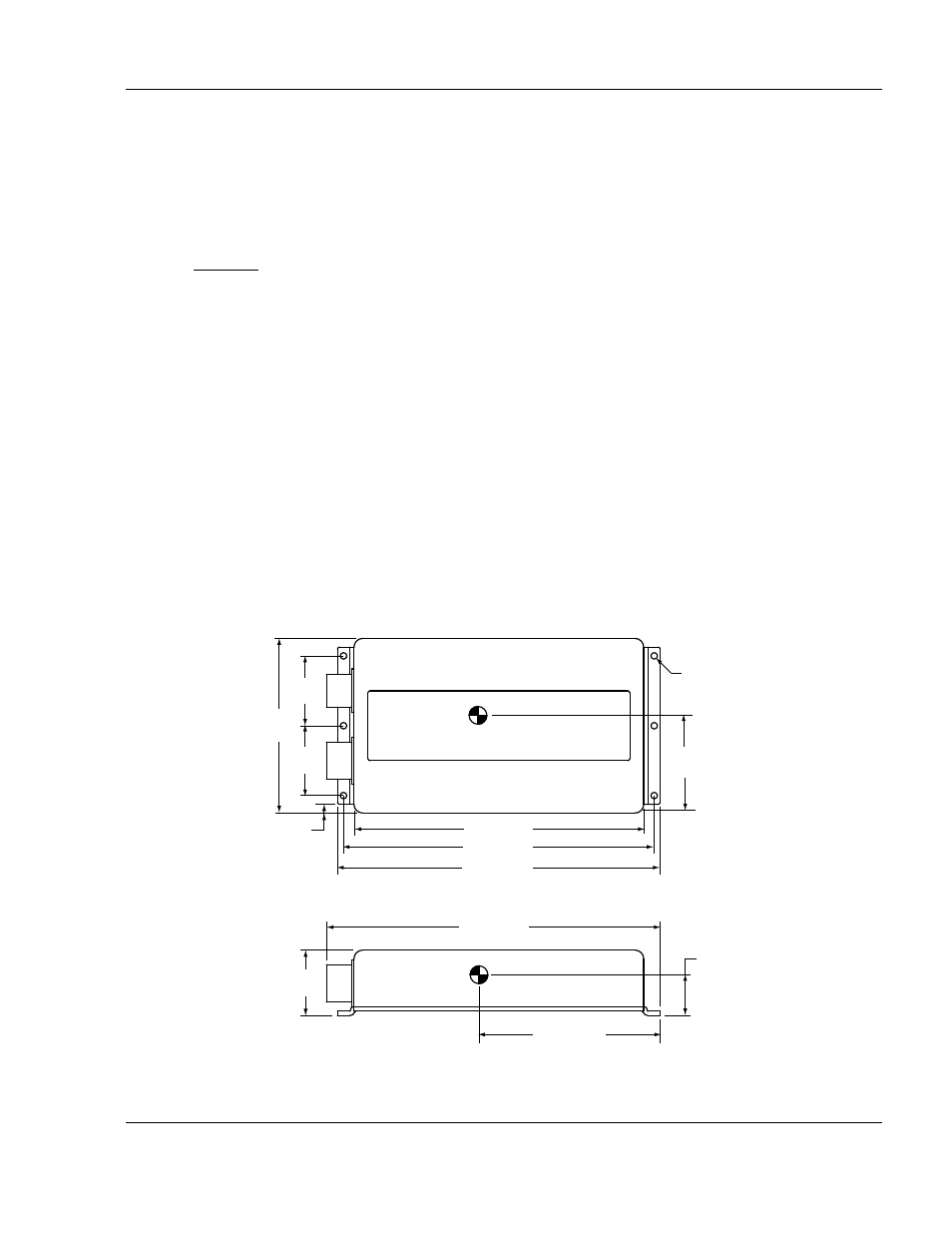
See "Figure 6. ELT/NAV Interface -B Outline and Dimensions".
Figure 6. ELT/NAV Interface -B Outline and Dimensions
2.00
(51)
2.00
(51)
5.00
(127)
8.30 (211)
8.90 (226)
9.25 (235)
2.75
(70)
9.57 (243)
1.15
(29)
5.27 (134)
1.88
(48)
Dimensions in inches (mm) - Tolerances ±0.020 (0.5) except as noted
453-6500
0.25
(6)
P1
P2
Ø 0.187 (4.7)
±0.005 (0.13)
(6 PLCS)