Pc 5153 – Acnodes PC 5153 User Manual
Page 46
14628 Central Blvd,
Chino, CA91710
tel:909.597.7588, fax:909.597.1939
© Copyright 2011 Acnodes, Inc.
All rights reserved. Product descrions
are subject to change without nomation,
please visit Acnodes’ web site at
PC 5153
15” Industrial wi
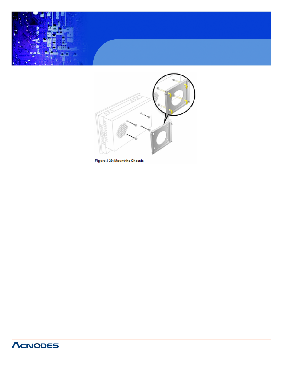
Step 9: Secure the panel PC with the wall-mounting kit. To do ttective
cushion to the wall-mounting kit first. Then, put the wall-mountinganel of
the panel PC. Carefully mark the location of the wall-mounting kit the
wall. Drill a pilot hole at the marked location on the wall. Secure t kit to
the wall by inserting a retention screw into the pilot hole on the w. This
step is to avoid the panel PC being pushed apart from the wall-t acci-
dentally.
4.11.2 Panel/ Mounting
To mount the PC5153/ PC5173 flat panel PC into a panel, pleasps be-
low.
NOTE:
The maximum panel thickness should be no more than 6 mm.
Step 1: Select the position on the panel to mount the PC5153/
Step 2: Cut out a section of the panel that corresponds to the rsions of
the PC5153/ PC5173. The recommended cutout sizes are sho 4-31,
Figure 4-32 and Figure 4-33).