Acnodes FPC 5105 User Manual
Page 13
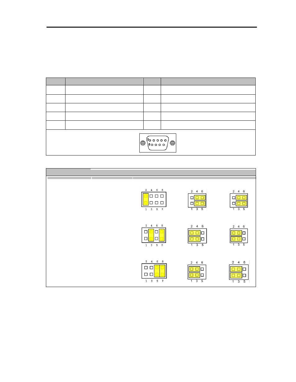
Pin
Signal
Pin
Signal
1
Data Carrier Detect (DCD)
6
Data Set Ready (DSR)
2
Receive Data (RXD)
7
Request To Send (RTS)
3
Transmit Data (TXD)
8
Clear To Send (CTS)
4
Data Terminal Ready (DTR)
9
Ring Indicator (RI)
5
Ground (GND)
Description
Function
Jumper Setting
COM 1
RS-232 (Default)
JP9
JP7
JP8
RS-422
JP9
JP7
JP8
RS-485
JP9
JP7
JP8
2.2
Serial Ports Interface
The FPC5105 has two onboard serial ports, COM1 (RS-232/ 422/ 485) and COM2 (RS-
232).
The following table shows you the pin assignments of this connector:
The following table shows you the pin assignments of this connector:
In addition, COM1 can be set for RS-232/422/485 by jumper. The jum p setting is listed as below:
- RMC 7182 (103 pages)
- PC 6170 (75 pages)
- PC6172 (66 pages)
- RMC 7132 (98 pages)
- RMC 7155 (5 pages)
- RMC 7150 (66 pages)
- PC 6152 (77 pages)
- PCH 5120 (82 pages)
- PC 8150 (72 pages)
- RMC 7130 (8 pages)
- RMC 7130 (99 pages)
- PC 8120 (7 pages)
- PC 8120 (51 pages)
- KD 6176 (3 pages)
- RMC 7155 (67 pages)
- FPC-8057 (57 pages)
- FPC 6084 (105 pages)
- FPC 7150 (80 pages)
- FES 6831 (50 pages)
- FES 5312 (117 pages)
- PCH 3982 (87 pages)
- PCH 7591 (99 pages)
- PC 5153 (97 pages)
- FPC 7919 (104 pages)
- FPC 6120 (114 pages)
- FPC 7615 (88 pages)
- PCH 7791 (99 pages)
- FES 2213 (57 pages)
- FES 2236 (49 pages)
- PCH 7991 (99 pages)
- PC 6408 (98 pages)
- FPC 7617 (88 pages)
- FPC 1015 (13 pages)
- FES 7510 (107 pages)
- PCH 3598 (82 pages)
- FPC 7161 (40 pages)
- PC 6172 (48 pages)
- PC 8153 (46 pages)
- FES 8730 (71 pages)
- PC 5192 (104 pages)
- PCH 3991 (77 pages)
- FES 6911 (58 pages)
- FES 2215 (37 pages)
- PC 6412 (107 pages)