Accusys ACS-76130 User Manual
Page 10
Disk Activity Indicators
These indicators show the status of each individual disk drive.
Indicator
Disk Activity
Green
Disk drive is properly installed and locked
Amber
Disk drive is being accessed
Red
Disk drive is not present, is not properly
installed, is unlocked, or disk has failed
Red Flashing
Disk drive is rebuilding data
In the event that a drive fails, the Red indicator turns on and an alarm sounds. You can turn off
the alarm by unlocking the drive carrier.
The drive carrier lock acts as an On/Off switch for the drives and
provides security by preventing non-key holders from accessing the
drives.
To lock each carrier, insert the key and turn it in a clockwise
direction. To unlock a carrier, turn the key in a counterclockwise
direction.
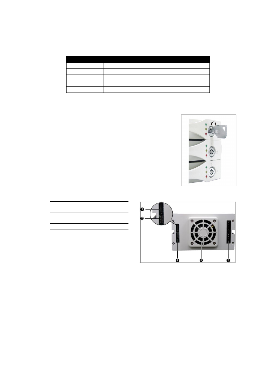
Rear view
Connector for SATA interface
cable
RAID level configuration jumper
pins
Power connector
3-pin RS232 connector (Terminal
port)
Cooling fan vent
The SATA cable is the route used for reading and writing to the array.
The power connector supplies power to the RAID box. In order to provide stable power, we
recommend to connect both power connectors on the RAID box.
The 3-pin RS-232 cable is used for remote monitoring of ACS-76130. The RS-232 port is
configured with DTE and PC compatible pin assignments.
There is a triangular symbol “▲” on both PCB connector and RS-232 cable connector,
please make sure you connect in the right direction (both triangle symbols match each
other). Connecting in wrong direction will not damage RAID controller, however the terminal
or GUI will not work.
The cooling fan inside the RAID box provides air circulation for the disk drives.