Connecting the fcs-320-tp/-tt series, Parameter settings using the dip switch, Commissioning – Bosch FCS-320-TP Series Conventional Aspirating Smoke Detectors User Manual
Page 27
FCS-320-TP1 | FCS-320-TP2 | FCS-320-TT1 | FCS-320-TT2
en
27
Bosch Sicherheitssysteme GmbH
F.01U.130.927 | 2.0 | 2010.12
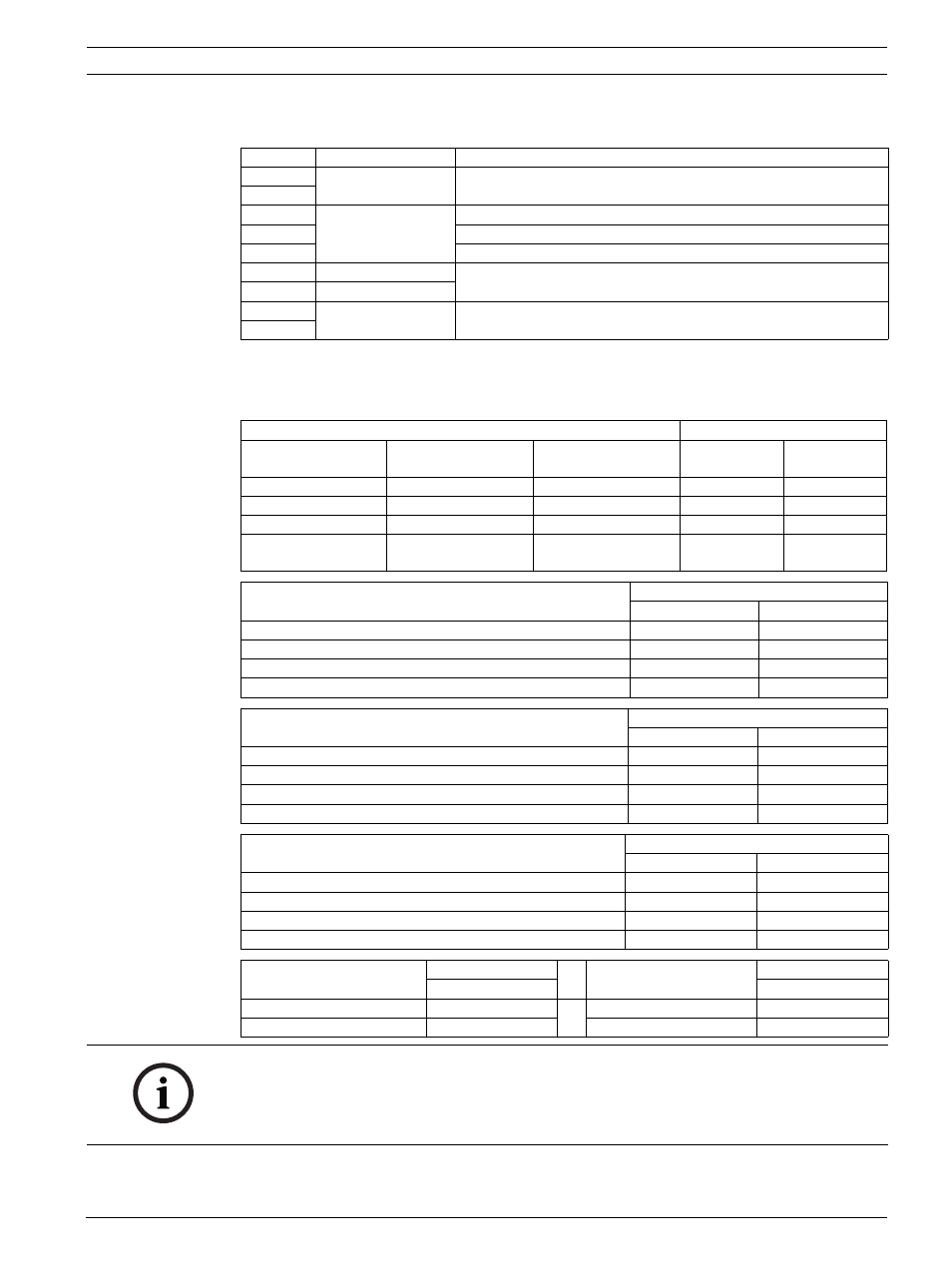
Connecting the FCS-320-TP/-TT series
See Figure 4, Page 5:
Parameter Settings Using the DIP Switch
The aspirating smoke detector parameters are set using the DIP switch on the detector
modules. The default settings are marked in bold in each case. Select all other parameters
(see tables).
Commissioning
See Figure 5, Page 5:
Terminal Terminal block X7
1
Fault 2
Fault contact for 2nd detector module
2
3
Al 2
NO contact for 2nd alarm relay
4
C contact for 2nd alarm relay
5
NC contact for 2nd alarm relay
6
+ Ext. Displ.2
Remote indicator for 2nd detector module
7
- Ext. Displ.2
8
Fault 1
Fault contact for 1st detector module
9
Sensitivity
DIP settings
DM-TP-01(05)
DM-TT-01(05)
DM-TP10(25)
DM-TT-10(25)
DM-TP50(80)
DM-TT-50(80)
Switch 1
Switch 2
0,12 %/m(0,4 %/m) 0,8 %/m(2 %/m)
on
on
0,06 %/m(0,2 %/m) 0,4 %/m(1 %/m)
off
on
0,03 %/m(0,1 %/m) 0,2 %/m(0,5 %/m)
1,0 %/m(1,6 %/m)
on
off
0,015 %/m(0,05 %/
m)
0,1 %/m(0,25 %/m) 0,5 %/m(0,8 %/m)
off
off
Alarm delay
DIP settings
Switch 3
Switch 4
0 seconds
off
off
10 seconds
on
off
30 seconds
off
on
60 seconds
on
on
Activation threshold for airflow malfunction
DIP settings
Switch 5
Switch 6
Low (+/- 10% volume flow change)
on
off
Average (+/- 20% volume flow change)
off
on
High (+/- 30% volume flow change)
off
off
Very high (+/- 50% volume flow change)
on
on
Airflow fault delay
DIP settings
Switch 7
Switch 8
30 seconds
off
on
2 minutes
on
off
15 minutes
on
on
60 minutes
off
off
Trouble logging
DIP settings
LOGIC·SENS filter
DIP settings
Switch 9
Switch 10
not saving
off
off
off
saving
on
on
on
NOTICE!
The sensitivity value is based on measurements with standard test fires (old value in
brackets).
The activation threshold for the airflow malfunction is set to 20% volume flow change by
default. Higher values are not permitted within EN 54-20.