Installation maintenance 14. maintenance – STIEBEL ELTRON psh 30 trend User Manual
Page 22
22
| PSH Trend www.stiebel-eltron.com
inSTALLATion
Maintenance
14. maintenance
WARNING Electrocution
Carry out all electrical connection and installation work
in accordance with relevant regulations.
Before any work on the appliance, disconnect all poles
of the appliance from the power supply.
If you need to drain the appliance, observe chapter "Draining the
appliance".
14.1 checking the safety valve
f
f Test the safety valve regularly.
14.2 draining the appliance
WARNING Burns
Hot water may escape during the draining process.
If is necessary to drain the cylinder for maintenance or to protect
the whole installation from frost, proceed as follows:
f
f Close the shut-off valve in the cold water feed line.
f
f Open the DHW valves of all draw-off points until the appli-
ance is fully drained.
f
f Drain any residual water from the safety valve.
14.3 checking / replacing the protective anode
f
f Check the protective anode after the first year of use and re-
place if necessary.
f
f Next, decide the time intervals at which further checks
should be carried out.
14.4 descaling
f
f Remove loose scale deposits from the water heater.
f
f If necessary, descale the inner cylinder with commercially
available descaling agents.
f
f Only descale the flange after disassembly and never treat the
cylinder surface and protective anode with descaling agents.
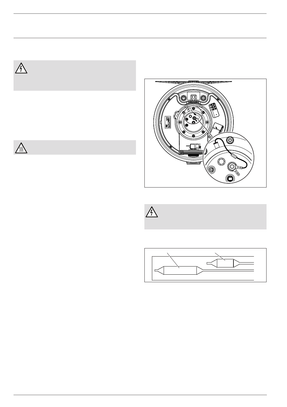
14.5 anti-corrosion protection
Ensure that while carrying out maintenance work the anti-corro-
sion protection (560 Ω) is not damaged or removed. Reinsert the
anti-corrosion protection correctly after replacement.
D
00000
37
14
1
14.6 replacing the power cable
DANGER Electrocution
The power cable must only be replaced (for example
if damaged) with the original spare part by a qualified
contractor authorised by the manufacturer.
14.7 replacing the combined controller/limiter
D
00000
37
14
2
2
1
1 Controller sensor
2 Limiter sensor
f
f Insert the controller sensor and the limiter sensor into the
sensor well as far as they will go.