18 belt drive blower motor and drive data, 19 static resistances, 20 electric heater cfm limitations – York BP 036 User Manual
Page 24: Table 18: belt drive blower motor and drive data, Table 19: static resistances, Table 20: electric heater cfm limitations
255027-YTG-B-0507
24
Unitary Products Group
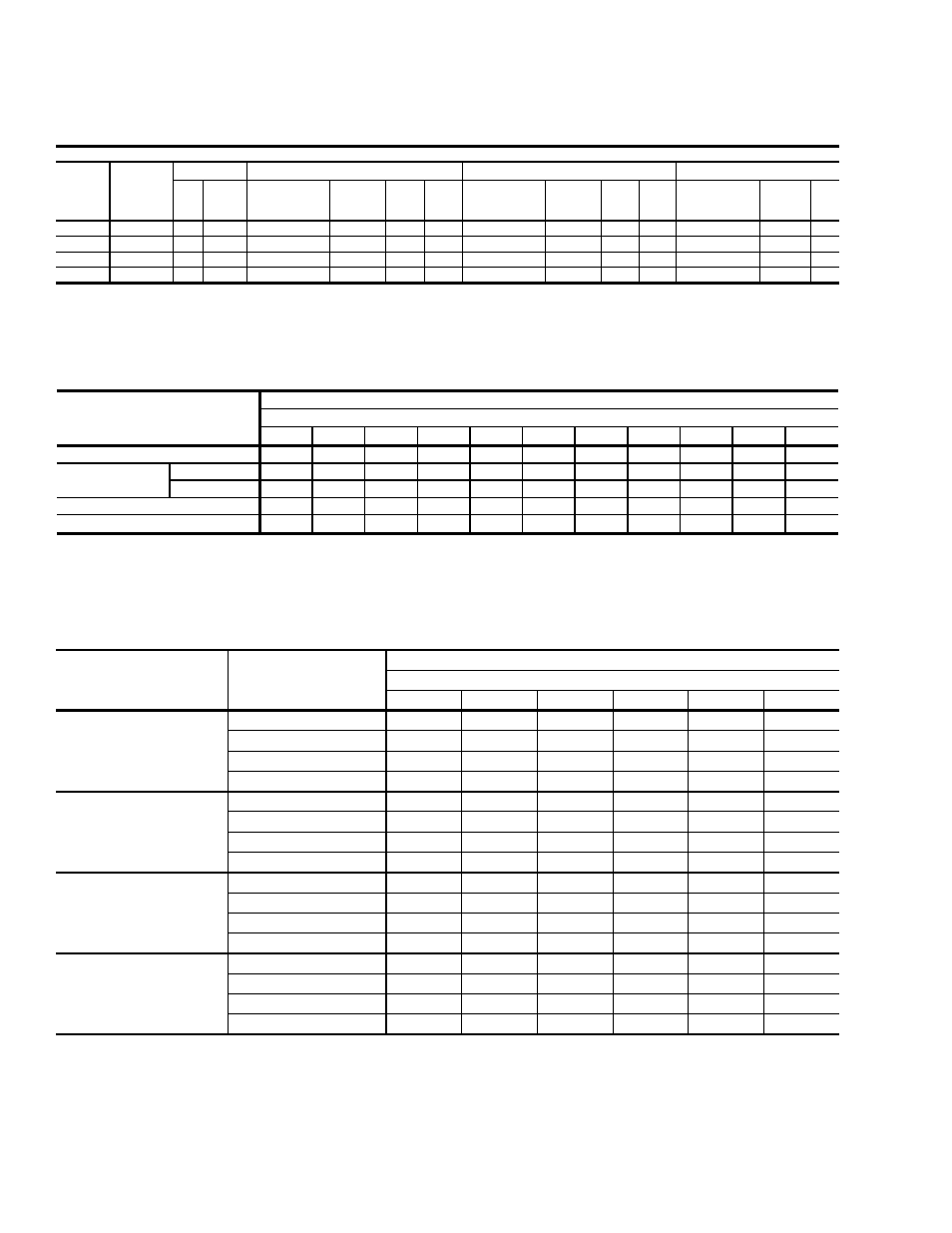
TABLE 18: BELT DRIVE BLOWER MOTOR AND DRIVE DATA
INDOOR BLOWER SPECIFICATION
MODEL
SIZE
BLOWER
RANGE
(RPM)
MOTOR
1
ADJUSTABLE MOTOR PULLEY
FIXED BLOWER PULLEY
BELT (NOTCHED)
HP FRAME DESIGNATION
OUTSIDE
DIA.
(IN.)
PITCH
DIA.
(IN.)
BORE
(IN.)
DESIGNATION
OUTSIDE
DIA.
(IN.)
PITCH
DIA.
(IN.)
BORE
(IN.)
DESIGNATION
PITCH
LENGTH
(IN.)
QTY.
036
600/920
1 1/2
56
1VL40
2.7-3.7
2.4-3.4
5/8
AK74
7.2
7.0
1
A39
40.3
1
048
790/1120
1 1/2
56
1VL40
2.7-3.7
2.4-3.4
5/8
AK61
5.9
5.7
1
A36
37.3
1
060
850/1220
1 1/2
56
1VL40
2.7-3.7
2.4-3.4
5/8
AK56
5.4
5.2
1
A36
37.3
1
072
900/1250
1 1/2
56
1VL44
3.1-4.1
2.8-3.8
7/8
AK56
5.4
5.2
1
A36
37.3
1
1. All motors have solid bases and are inherently protected. these motors can be selected to operate into their service factor because they are located
in the moving air, upstream of any heating device.
TABLE 19: STATIC RESISTANCES
1000
1200
1400
1600
1800
2000
2200
2400
2600
2800
3000
0.07
0.08
0.09
0.11
0.13
0.15
0.17
0.20
0.23
0.26
0.30
7-15KW
0.04
0.05
0.06
0.07
0.08
0.10
0.12
0.14
0.16
0.19
0.22
20-30KW
0.06
0.07
0.08
0.09
0.11
0.13
0.15
0.17
0.20
0.23
0.26
0.06
0.07
0.08
0.09
0.10
0.11
0.12
0.14
0.16
0.19
0.22
0.08
0.10
0.12
0.14
0.16
0.18
0.20
0.23
0.26
0.29
0.32
COOLING ONLY
2
RESISTANCE, IWG
CFM
DESCRIPTION
ECONOMIZER
1 3
BOTTOM DUCT CONNECTIONS
1
ELECTRIC
HEATERS
1
1. Deduct these resistance values from the available external static pressure shown in SUPPLY AIR BLOWER PERFORMANCE Tables.
3. The pressure through the economizer is greater for 100% outdoor air than for 100% return air. If the resistance of the return air
duct system is less than 0.25 IWG, the unit will deliver less CFM during full economizer operation.
2. Add these resistance values to the available static resistance values on SUPPLY AIR BLOWER PERFORMANCE Tables.
TABLE 20: ELECTRIC HEATER CFM LIMITATIONS
UNIT MODEL SIZE
NOMINAL TONS
VOLTAGE
MINIMUM SUPPLY AIR CFM
HEATER SIZE NOMINAL KW
5
7
10
15
20
30
036
(3)
208/230-1-60
1100
1100
1200
1200
1300
-
208/230-3-60
1100
1100
1200
1200
1300
-
460-3-60
-
1100
1200
1200
1300
-
575-3-60
-
-
1200
1200
1300
-
048
(4)
208/230-1-60
1300
1300
1300
1300
1300
-
208/230-3-60
1300
1300
1300
1300
1300
-
460-3-60
-
1300
1300
1300
1300
-
575-3-60
-
-
1300
1300
1400
-
060
(5)
208/230-1-60
1600
1600
1600
1600
1600
1600
208/230-3-60
1600
1600
1600
1600
1600
1600
460-3-60
1600
1600
1600
1600
1600
1600
575-3-60
-
1600
1600
1600
1600
1800
072
(6)
208/230-1-60
1800
1800
1800
1800
1800
1800
208/230-3-60
1800
1800
1800
1800
1800
1800
460-3-60
-
1800
1800
1800
1800
1800
575-3-60
-
-
1800
1800
1800
1800