Figure 2, Shows two, Earl y access – Xilinx LogiCore PLB PCI Full Bridge User Manual
Page 6
PLB PCI Full Bridge (v1.00a)
6
w.xilinx.com
DS508 March 21, 2006
Product Specification
EARL
Y ACCESS
Example 3 outlines the use of the PCIBAR parameter sets for the address translation of PCI addresses
within the range of a given PCIBAR to a remote PLB address space.
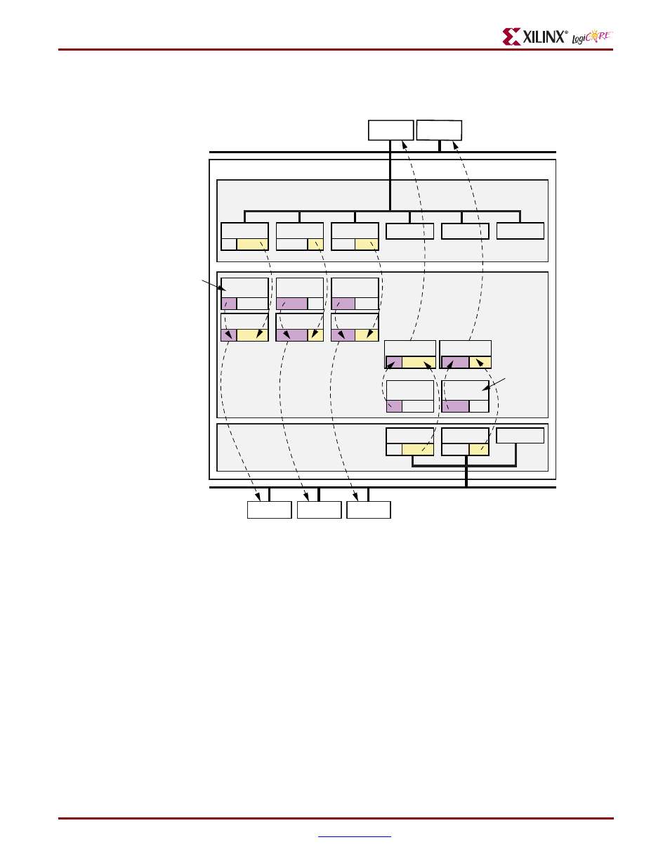
Figure 2: Translation of Addresses Bus-to-Bus with High-Order Bit Substitution
Figure Top x-ref 2
PLB PCI Full Bridge
PLB Bus
Note 2
BAR_11
BAR_10
IPIF
C_IPIFBAR_NUM = 3
IPIFBAR_3
IPIFBAR_4
IPIFBAR_5
IPIF to v3.0 LogiCORE Bridge
v3.0 LogiCORE
C_PCIBAR_NUM = 2
PBAR_21
PBAR_22
PBAR_20
PCI Bus
Note 1
(high-order
bit sub)
Addr to PCI
IPIFBAR_0
(high-order
bit sub)
Addr to PCI
IPIFBAR_1
(high-order
bit sub)
Addr to PLB
PCIBAR_0
(high-order
bit sub)
Addr to PLB
PCIBAR_1
(high-order
bit sub)
Addr to PCI
IPIFBAR_2
PCIBAR_2
ds508_02_112205
Example 1
Because address translations are performed only when the PLB PCI Bridge is configured with FIFOs,
the example shown in
is for an PLB PCI Bridge configuration with FIFOs only. In this example, it
is assumed that C_INCLUDE_BAROFFSET_REG=0, therefore, the parameters C_IPIFBAR2PCIBAR_N
define the high-order bits for substitution in translating the address on the PLB bus to the PCI bus.
The PLB parameters are C_IPIFBAR_N, C_IPIF_HIGHADDR_N, and C_IPIFBAR2PCIBAR_N for N=0
to 5.
The PCI parameters are C_PCIBAR_LEN_M and C_PCIBAR2IPIFBAR_M for M=0 to 2.
Example 2
Example 2 shows of the settings of the two independent sets of base address register (BAR) parameters
for specifics of address translation of PLB addresses within the range of a given IPIFBAR to a remote
PCI address space. Note that this setting does not depend on the PCIBARs of the PLB PCI Bridge.