3 rear panel, 4 front panel – ZyXEL Communications GS-1124A User Manual
Page 19
Dimension GS-1116A/GS-1124A Gigabit Switch
Hardware Description and Installation
2-3
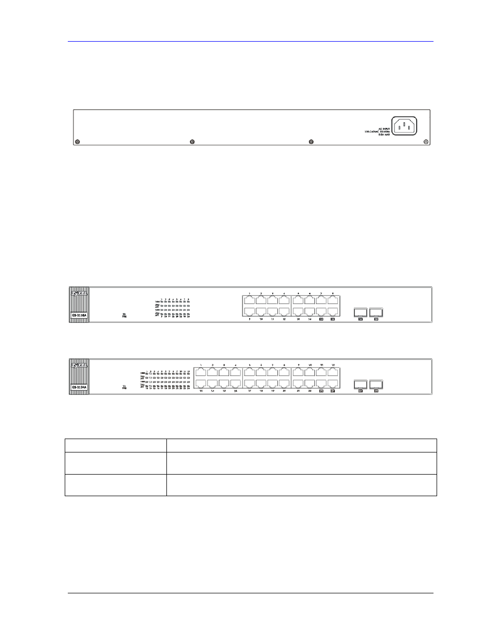
2.3 Rear
Panel
The ventilation fan and three-pronged power receptacle are located on the rear panel of the switch.
Figure 2-4 Switch Rear Panel
2.3.1 Rear Panel Power Connection
Connect one end of the supplied power cord to the power receptacle on the back of the switch and the
other end to the 100-240 VAC, 50-60 Hz power source. Push the power switch to the ON position.
2.4 Front
Panel
The following graphics show the front panels of the GS-1116A and the GS-1124A.
Figure 2-5 GS-1116A Front Panel
Figure 2-6 GS-1124A Front Panel
Table 2-1 GS-1116A/GS-1124A: Front Panel Ports
CONNECTOR DESCRIPTION
RJ-45 ports
Connect these 100/1000 Mbps RJ-45 Ethernet ports to computers, hubs, Ethernet
switches or routers.
Mini GBIC ports
Use mini GBIC transceivers in these ports for fiber-optical connections to
backbone Ethernet switches.
2.4.1 100/1000Mbps RJ-45 Auto-negotiating Ports
The GS-1116A has 16 100/1000 Mbps RJ-45 ports. The GS-1124A has twenty-four 100/1000 Mbps
RJ-45 ports. The auto-negotiation feature allows the switches to detect the speed of incoming
transmission and adjust appropriately without manual intervention. It allows data transfers of either
• 100Mbps in half-duplex mode