Installation ) – Yamaha CRW8424E User Manual
Page 26
Installation
)
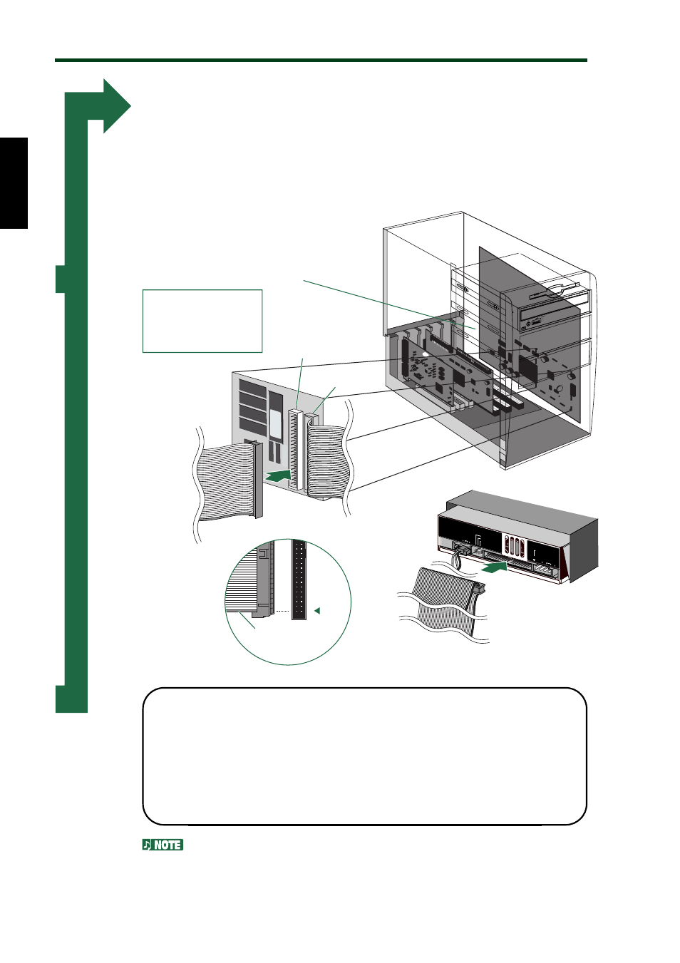
Connect the IDE cable.
Connect the included 40-pin IDE cable to the secondary IDE
connector on the motherboard and to the IDE interface connector
on the rear panel of the CRW8424E. Be sure to plug in the cable so
that the colored line on the cable corresponds to pin #1 on the right
end of the connector.
Motherboard
Included IDE cable
Included IDE cable
Magnified IDE
connector
section
IDE
INTERF
ACE
CONNECT
OR
DC IN
PUT
1
+5V
G
+12V
CSEL
SLA
VE
MASTER
AUDIO OUT
R
L
G
Colored line
Primary
(connector)
Secondary
(connector)
1
• If an IDE cable has already been connected to the secondary
IDE connector, replace it with the included IDE cable.
• If you wish to continue using the IDE device you just removed,
connect it to an available primary or secondary IDE connector.
• When you connect two IDE devices to one IDE cable, be sure
to assign them master or slave uniquely.
To make the best use of the performance of the CRW8424E, Yamaha
recommends you connect it as a sole secondary master.
17