Wiring connections, Single stage connections – White Rodgers 1F97-1277 User Manual
Page 3
3
Single
Stage
(SS)
Energized
in Cool
Mode
Energized
in Heat,
Off Mode
System
O
RH
+
B
CLASS II
TRANSFORMER
HOT
24VAC
NEUTRAL
120VAC
W
G
C*
-
Energized
on call
for Cool
(Com-
pressor)
Blower/
Circula-
tor Fan
Energiz-
ed on
call for
Heat or
Cool
(if ELE
is sel-
ected)
24 Volt
(Hot)
Cool
DC
supply
voltage
to re-
mote
Temp-
erature
Sensor
Remote
Temp-
erature
Sensor
signal
DC
Return
to
Remote
Temp-
erature
Sensor
Energized
on call for
Heat
Third wire
for 3-wire
zone valve
Y
RC
S
6
L
{
To Remote Temperature Sensor
24 Volt
(Hot)
Heat
24 Volt
Com-
mon
(option-
al)
CLASS II
TRANSFORMER
120VAC
HOT
24VAC
NEUTRAL
HEATING
COOLING
Diagnostic
Indicator
(See
Note
)
1
Jumper
Remove Jumper Wire
between RH & RC
Single
Stage
(SS)
Energiz-
ed in
Cool
Mode
Energized
in Heat
or Off
Mode
System
O
RH
+
B
CLASS II
TRANSFORMER
HOT
24VAC
NEUTRAL
120VAC
W
G
C*
-
Jumper
Energized
on call
for Cool
(Com-
pressor)
Blower/
Circula-
tor Fan
Energiz-
ed on
call for
Cool &
for Heat
(if ELE
is sel-
ected)
24 Volt
(Hot)
Cool
DC
supply
voltage
to re-
mote
Temp-
erature
Sensor
Remote
Temp-
erature
Sensor
signal
DC
Return
to
Remote
Temp-
erature
Sensor
Energized
on call for
Heat
Third
wire for
3-wire
zone
valve
Diagnostic
Indicator
(See
Note
)
Y
RC
S
6
L
{
To Remote Temperature Sensor
24 Volt
(Hot)
Heat
24 Volt
Com-
mon
(option-
al)
1
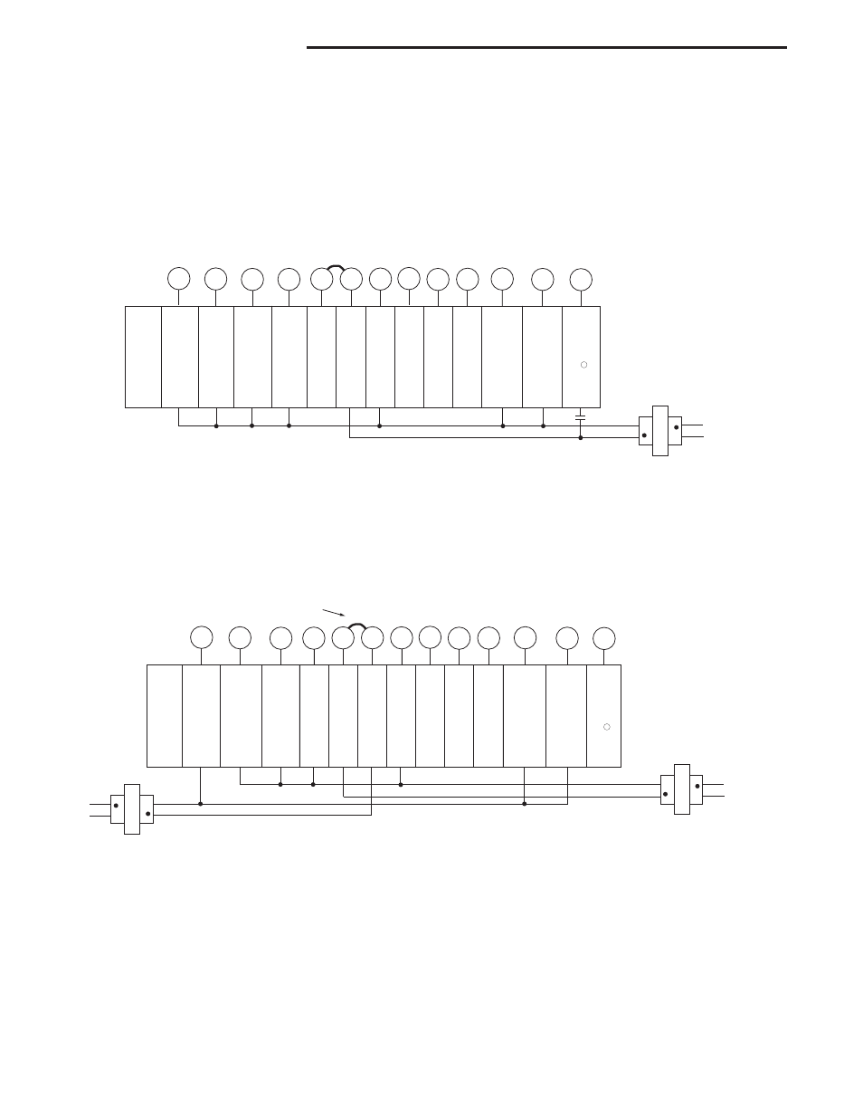
Single Stage Connections
Refer to equipment manufacturers' instructions for specific system
wiring information .
This thermostat is designed to operate a single-transformer or two-
transformer system .
You can configure the thermostat for use with the following systems:
SINGLE STAGE gas, oil or electric .
After wiring, see INSTALLER CONFIGURATION section for proper
thermostat configuration.
Single Stage System with Single Transformer
Single Stage with Two Transformers
* Common connection
required for fault or
malfunction indication
and remote sensor .
NOTE: If continuous backlight or hardwired
power input are desired but do not function
in both HEAT and COOL modes, cut the
heating transformer 24V wires and tape off .
Connect the neutral circuit disconnected
from the heating transformer to the neutral
circuit of the cooling transformer . Discon-
nect the wire to the RH terminal and install
a jumper between RH and RC . Depending
on the system requirements, replace the
cooling transformer with a 75VA class II
transformer if needed .
WIRING CONNECTIONS
* Common connection
required for fault or
malfunction indication
and remote sensor .
NOTE ➀: Connection for Call for Service diagnostic indicator compatible with mechanical or electronic condenser control with Comfort Alert
TM
.