Warning, Wiring connections, Installation – White Rodgers 1F97-1277 User Manual
Page 2: Battery location, Remove old thermostat, Installing new thermostat
2
2 "AA" Batteries
WIRING CONNECTIONS
Refer to equipment manufacturers' instructions for specific
system wiring information . After wiring, see CONFIGURA-
TION section for proper thermostat configuration.
For wiring diagrams, see next page .
Wiring diagrams shown are for typical systems and describe
the thermostat terminal functions .
INSTALLATION
Battery Location
2 "AA" alkaline batteries are included in the thermostat at
the factory with a battery tag to prevent power drainage .
Remove the battery tag to engage the batteries .
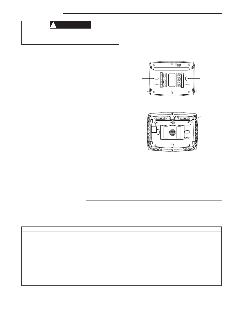
To replace batteries, set system to OFF, remove thermostat
from wall and install the batteries in the rear along the top of
the thermostat (see Figure 1) .
Remove Old Thermostat
A standard heat/cool thermostat consists of three basic parts:
1 . The cover, which may be either a snap-on or hinge type .
2 . The base, which is removed by loosening all captive
screws .
3 . The switching subbase, which is removed by unscrewing
the mounting screws that hold it on the wall or adapter
plate .
Before removing wires from old thermostat,
label each wire with the terminal designation from
which it was attached. Disconnect the wires from the old
thermostat one at a time .
Do not let wires fall back into
the wall.
Installing New Thermostat
1 . Pull the thermostat body off the thermostat base . Forcing
or prying on the thermostat will cause damage to the unit .
2 . Place base over hole in wall and mark mounting hole
locations on wall using base as a template .
3 . Move base out of the way . Drill mounting holes . If you
are using existing mounting holes and the holes drilled
are too large and do not allow you to tighten base snugly,
use plastic screw anchors to secure the base .
4 . Fasten base snugly to wall using mounting holes shown
in Figure 1 and two mounting screws . Leveling is for
appearance only and will not affect thermostat operation .
5 . Connect wires to terminal block on base using appropriate
wiring schematic (see diagrams on next page) .
6. Push excess wire into wall and plug hole with a fire resis-
tant material (such as fiberglass insulation) to prevent
drafts from affecting thermostat operation .
7 . Carefully line the thermostat up with the base and snap
into place .
Terminal Designation
Description
B . . . . . . . . . . . . . . . . . . . Changeover valve for heat pump energized constantly in heating
O . . . . . . . . . . . . . . . . . . . Changeover valve for heat pump energized constantly in cooling
Y . . . . . . . . . . . . . . . . . . . Compressor Relay
G . . . . . . . . . . . . . . . . . . . Fan Relay
RC . . . . . . . . . . . . . . . . . . . Power for Cooling
RH . . . . . . . . . . . . . . . . . . . Power for Heating
C . . . . . . . . . . . . . . . . . . . Common wire from secondary side of cooling
L . . . . . . . . . . . . . . . . . . . For Call for Service indicator for systems with diagnostic connection
6 . . . . . . . . . . . . . . . . . . . Powered closed connection for 3-wire zone valve
W . . . . . . . . . . . . . . . . . . . Heat Relay
- . . . . . . . . . . . . . . . . . . . . Common (DC) for wired remote temperature sensor
S . . . . . . . . . . . . . . . . . . . Frequency signal from remote temperature sensor
+ . . . . . . . . . . . . . . . . . . . Power (DC) to remote temperature sensor
TERMINAL DESIGNATION DESCRIPTIONS
Mounting
Hole
Mounting
Hole
Place Level
across
Mounting Tabs
(for appearance only)
Place Level
across
Mounting Tabs
(for appearance only)
+
S
-
W/E
6
L
Figure 1 – Thermostat Base Multi-Stage 1F97-1277
Rear view of thermostat
WARNING
!
Thermostat installation and all components of the
control system shall conform to Class II circuits per
the NEC code.