White Outdoor 693 User Manual
Page 14
14
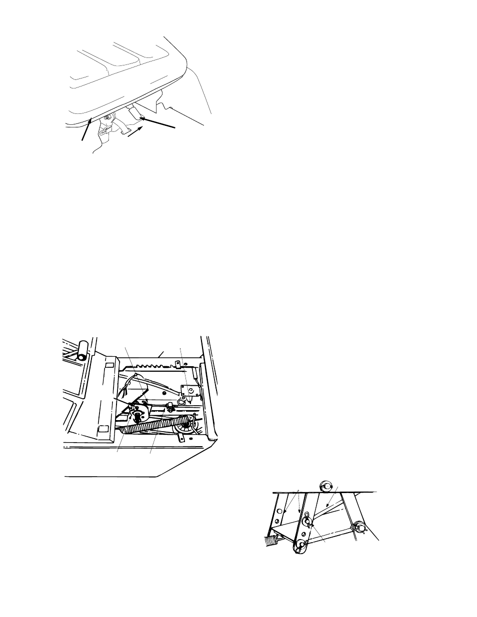
Figure 14
HYDROSTATIC NEUTRAL CONTROL
ADJUSTMENT
The hydrostatic transmission control is in correct
adjustment when the tractor does not move with the
engine running, the clutch engaged and the
hydrostatic control lever in the neutral position.
If adjustment is necessary, follow these steps:
1.
Raise both rear wheels off the ground by placing
blocks under the rear frame.
2.
Remove transmission panel by removing the
parking brake knob, rubber boot on relief valve
and truss machine screws.
3.
Loosen the hex jam nut on the speed selector
adjusting rod. See Figure 15.
Figure 15
4.
Loosen the hex nut on the scissor mounting
bracket. See Figure 15.
5.
Start the engine and run at full throttle.
6.
Move the hydrostatic control lever until you find
neutral (rear wheels do not rotate in either
direction).
7.
Depress the clutch-brake pedal until the scissor
brackets come together.
8.
Shut off the engine.
9.
Tighten hex nut on the scissor mounting bracket.
10. Thread the speed selector rod in or out of the
ferrule until the hydrostatic control lever lines up
in the neutral position on the speed control index
bracket.
11. Tighten hex jam nut against the ferrule.
12. Replace the transmission panel, rubber boot on
relief valve and parking brake knob.
13. Remove the blocks from under the frame and
test the operation of the tractor.
DECK LEVELING ADJUSTMENT
If an uneven cut is obtained, the deck may be
leveled by following instructions in Assembly section.
DECK ENGAGEMENT ADJUSTMENT
The cutting deck engagement may be adjusted to
make certain deck is disengaged when lift lever is in
the BLADES STOP position. Correct adjustment as
follows.
With the engine off, place the lift lever in the highest
cutting position (first position). Remove the cotter pin
and flat washer which secure the disengagement rod
to the stabilizer shaft assembly. See Figure 16.
Shorten the rod by threading it in until the ferrule is
against the back of the slot in the lift shaft assembly,
and the rod lines up with the hole in the stabilizer
shaft. For more belt tension the disengagement rod
must be lengthened. To decrease belt tension the
disengagement rod must be shortened.
Check the adjustment by placing the lift lever in the
BLADES STOP position. The deck should move up
and forward, allowing the belt to become loose. Start
and test for disengagement. Repeat procedure as
necessary.
Figure 16
Seat
Adjustment
Lever
Seat
Scissor
Bracket
Mounting
Hex Jam Nut
(Loosen
)
Scissor
Bracket
Speed Selector
Adjusting Rod
Hex Nut
(Loosen)
Flat Washer
Hairpin Clip
Disengagement Rod
Stabilizer Shaft
Assembly