Wiring diagrams – White Rodgers 1F85-0477 User Manual
Page 3
3
Single
Stage 1
(SS1)
Multi-
Stage 2
(MS2)
O
Energized Constantly
in Cool Mode
B
Energized Constantly
in Heat, Off,
Emergency
Mode
No
Output
Cool
Mode
2nd
Stage
Cool Mode
1st Stage
Blower/
Circulator
Fan Energized
on Call for
Cool (and
Heat if
configured
for Electric
Heat)
No Output
Heat Mode
2nd Stage
Heat
Mode
1st Stage
Optional*
24 Volt
(Com-
mon)
24 Volt
(Hot)
Cool
System
Y
G
W/E
C
L
RC
CLASS II
TRANSFORMER
HOT
24VAC
NEUTRAL
120VAC
24 Volt
(Hot)
Heat
RH
Y2
W2
Jumper
Fault
Indicator
or
System
Malfunction
Switch
System Malfunction
Module
O/B
WIRING DIAGRAMS
Heat Pump Connections
If you do not have a heat pump system, refer to figures 4-6.
Refer to equipment manufacturers’ instructions for specific
system wiring information.
You can configure the thermostat for use with the following
heat pump systems.
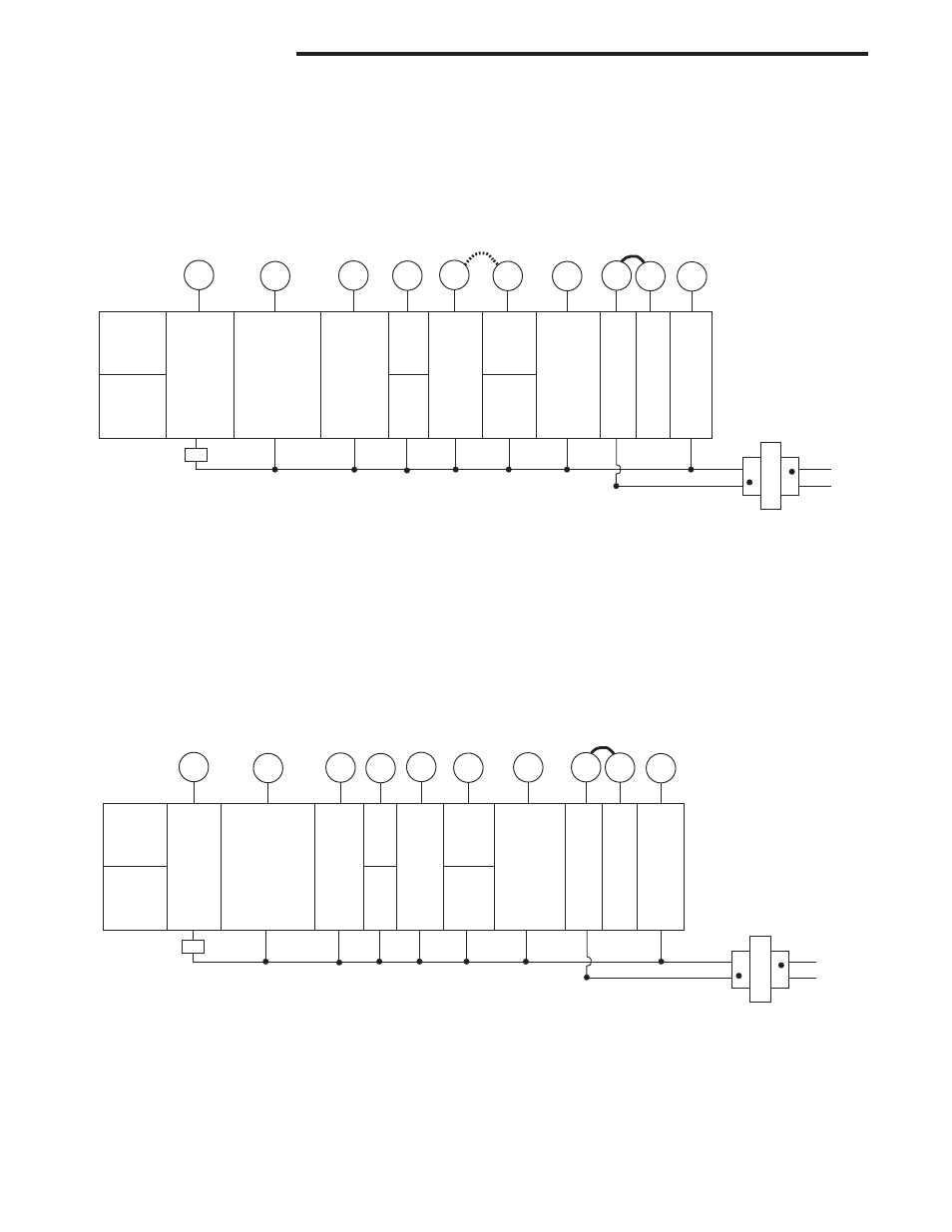
Figure 3 – Heat Pump Systems
HEAT PUMP TYPE 1 (HP 1). Single stage compressor
system; gas or electric backup.
HEAT PUMP TYPE 2 (HP 2). Multi-stage compressor or two
compressor system with gas or electric backup.
After wiring, see INSTALLER CONFIGURATION section for
proper thermostat configuration.
NOTE: If your system does
not provide an E connection,
jumper W2 to W/E to use
the Auxiliary Heat in the
Emergency Mode.
* Common connection
required for fault or
malfunction indication.
Heat Pump 2
(HP2)
Heat Pump 1
(HP1)
O
Energized in
Cool Mode
B
Energized in
Heat, Off,
Emergency
Mode
2nd
Stage
(Com-
pressor)
No
Output
Heat and
Cool Mode
1st Stage
(Compressor)
Blower/
Circulator
Fan Energized
on Call for
Heat or Cool.
Set Elect/Gas
Option for
Emergency
Mode
Heat Mode
2nd Stage.
Emergency
Mode 2nd
Stage
Heat Mode
3rd Stage.
Emergency
Mode 2nd
Stage
Emergency
Mode
1st Stage
Optional*
24 Volt
(Com-
mon)
Fault Indicator
or System
Malfunction
Switch
24 Volt
(Hot)
Cool
System
Y
W/E
C
L
RC
CLASS II
TRANSFORMER
HOT
24VAC
NEUTRAL
120VAC
24 Volt
(Hot)
Heat
RH
Jumper
Y2
W2
G
Jumper
Comfort Alert II Module
or Similar System
Malfunction Module
O/B
Single Stage and Multi-Stage Connections
Refer to equipment manufacturers’ instructions for specific
system wiring information.
This thermostat is designed to operate a single-transformer
or two-transformer system.
You can configure the thermostat for use with the following
fossil fuel systems:
SINGLE STAGE (SS 1) gas, oil or electric.
MULTI-STAGE (MS 2) gas, oil or electric.
After wiring, see INSTALLER CONFIGURATION section for
proper thermostat configuration.
Figure 4 – Single Stage or Multi-Stage System (No Heat Pump) with Single Transformer
* Common connection
required for fault or
malfunction indication.