Weider 831.15395.0 User Manual
Page 10
10
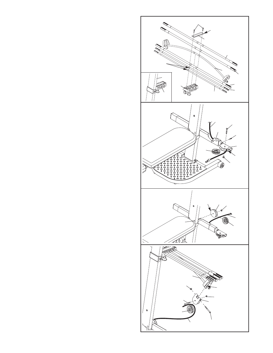
19. Attach a Pulley Housing (94) to the indicated “U”-
channel on the 10-Pound Center Resistance Bar
(44) with a 3/8” x 4” Bolt (66) and a 3/8” Nylon
Locknut (76).
Wrap the Long Cable (80) around a 90mm Pulley
(28). Attach the Pulley inside of the Pulley
Housing (94) with a 3/8” x 1 1/2” Button Head
Bolt (71) and a 3/8” Nylon Jamnut (103).
19
66
94
28
80
44
103
76
71
18. Wrap the Long Cable (80) around a 90mm Pulley
(28). Attach the Pulley and a Pulley Guard (29) to
the indicated 3/8” x 5 1/2” Carriage Bolt (73) with
a 3/8” Nylon Locknut (76).
Be sure the flat edge
of the Pulley Guard is on the side shown.
18
76
28
80
73
29
Flat
Edge
16
86
Edges
up
72
Rings on
this side
96
95
95
44
36
67
35
35
4
17.
Locate the Long Cable (80). Insert one end of
the Cable through the welded tube on the indicat-
ed end of the Cross Tube (11) and then through a
Swivel Arm (22). If necessary, use the tip of a
screwdriver to pull the end of the Cable out of the
Swivel Arm.
Be sure the Cable is on the indicat-
ed side of the welded rod in the Swivel Arm.
Insert the Swivel Arm (22) into the welded tube
on the Cross Tube (11). Secure the Swivel Arm
with a #8 x 3/8” Screw (24).
Wrap the Long Cable (80) around a 90mm Pulley
(28). Attach the Pulley inside of the Swivel Arm
(22) with a 3/8” x 1 1/2” Button Head Bolt (71)
and a 3/8” Nylon Jamnut (103).
17
71
22
24
28
80
11
103
Rod
“U”-Channel
16. Locate the Tray (35) on the Lat Tower (4) (see the
inset drawing). Remove the two preassembled
5/16” x 3/4” Button Head Screws (86) and the
Cover Plate (72) from the Tray.
Set the Resistance Bars into the Tray (35) in the
following order: the 10-Pound Removable
Resistance Bar (67), the 20-Pound Removable
Resistance Bar (36), an 80-Pound Resistance Bar
(95), the 10-Pound Center Resistance Bar (44), an
80-Pound Resistance Bar (95), and the 40-Pound
Resistance Bar (96).
Make sure the indicated
rings are on the side shown and the arrows
point toward the Tray.
Reattach the Cover Plate (72), with the edges up,
to the Tray (35) with two 5/16” x 3/4” Button Head
Screws (86).