System configuration, Operation, Set option switches – White Rodgers 1F95W-71 User Manual
Page 6: Attach thermostat to subbase
6
SYSTEM CONFIGURATION
ANY TIME OPTION SWITCHES #1 OR #2 ARE
CHANGED, THE 9 VOLT ENERGIZER
®
BATTERY MUST
BE REMOVED FOR A MINIMUM OF 2 MINUTES.
Set Option Switches
1.
For furnaces not requiring a G terminal to energize
fan (systems with fan/limit switch or automatic fan on/
off operation):
2.
For systems with electric furnace, and where blower
is energized through fan relay (no sequence to ener-
gize blower):
3.
For systems with an economizer for first stage cooling:
ENGAGE TWO UPPER GUIDES;
PIVOT DOWN
Figure 7. Attaching thermostat to subbase
Attach Thermostat To Subbase
WE RECOMMEND THAT YOU SET OPTION SWITCHES
TO DESIRED POSITION BEFORE ATTACHING ON
SUBBASE (see OPERATION). WE ALSO RECOM-
MEND THAT YOU PROGRAM THE THERMOSTAT
WITH BATTERY INSTALLED BEFORE ATTACHING
ON SUBBASE (see OPERATION GUIDE for program-
ming instructions).
USE
SYSTEM
HEAT - OFF - COOL - AUTO
TO TURN THERMOSTAT OFF BEFORE
ATTACHING THERMOSTAT TO WALL. FAILURE TO
TURN THERMOSTAT OFF MAY CAUSE EQUIPMENT
DAMAGE DUE TO RAPID COMPRESSOR CYCLING.
To attach thermostat to subbase, line up the plastic snap
guides at the top of the thermostat and the 4 connector
pins on the thermostat with the connectors near the top
right section of the subbase (when viewed from the front).
Gently pivot the thermostat down until the 8-pin connec-
tors and the plastic snaps lock into place (see fig. 7). Be
gentle when attaching thermostat. If the thermostat
does not seem to be attaching to the subbase easily,
make sure that the connector pins and plastic snaps are
properly aligned, and that excess wire is pushed into the
wall. Damage to the thermostat may occur if force is
used.
OPERATION
NOTE
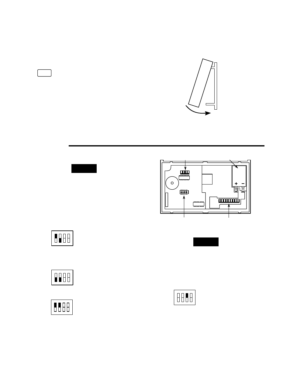
Figure 8. Back of thermostat
Option switches
9-pin connector
4-pin connector
Battery
Set option switches #1 and #2, install the battery, and
program the thermostat before changing option switch #3
or #4.
4.
To enable total keypad lockout (ALL buttons will be
disabled and will not operate until configuration is
changed):
Switch #3 in ON position disables all buttons.
ON
1
2
3
4
Switch #1 ON
Switch #2 (see step 3)
Switch #3 (see step 4)
Switch #4 (see step 5)
ON
1
2
3
4
Switch #1 OFF
Switch #2 (see step 3)
Switch #3 (see step 4)
Switch #4 (see step 5)
ON
1
2
3
4
Switch #1 (see steps 1 & 2)
Switch #2 ON
Switch #3 (see step 4)
Switch #4 (see step 5)
NOTE
ON
1
2
3
4
Switch #1 (see steps 1-2)
Switch #2 (see step3)
Switch #3
Switch #4 (see step 5)
ON