Warning ! caution – White Rodgers 1F95W-71 User Manual
Page 4
4
C
R
G
B
O
CHANGEOVER
ENERGIZED
IN HEAT
CHANGEOVER
ENERGIZED
IN COOL
COMPRESSOR
CONTACTOR
STAGE 1
FAN
RELAY
HEAT
RELAY
STAGE 1
HEAT
RELAY
STAGE 2
HEAT
RELAY
STAGE 3
THERMOSTAT
CONTROL
CIRCUIT
COMPRESSOR
CONTACTOR
STAGE 2
24 VAC
120 VAC
HOT
NEUTRAL
THERMOSTAT
SYSTEM
Y1
Y2
W1
W2
W3
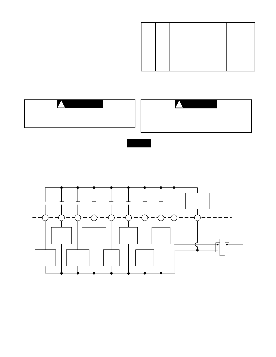
Figure 4. Typical wiring diagram for single transformer systems
To prevent electrical shock and/or equipment
damage, disconnect electrical power at the main
fuse box until installation is complete. Verify
power is off with a voltmeter.
DO NOT EXCEED MAXIMUM VOLTAGE OR CUR-
RENT RATINGS. FIRE, PERSONAL INJURY, AND/
OR EQUIPMENT DAMAGE COULD RESULT.
NOTE
TABLE 2. WIRE IDENTIFICATION LABELS
1
G
G
1
9
Y1
Y1
9
2
C
C
2
3
L
L
3
4
R
R
4
5
O
O
5
6
B
B
6
7
E1
E1
7
8
E2
E2
8
10
Y2
Y2
10
11
W1
W1
11
12
W2
W2
12
13
W3
W3
13
14
S1
S1
14
15
S2
S2
15
16
S3
S3
16
affect thermostat operation.) If you are using existing
mounting holes, or if holes drilled are too large and do
not allow you to tighten subbase snugly, use plastic
screw anchors to secure subbase.
6.
Push excess wire into wall and plug hole with a fire-
resistant material (such as fiberglass insulation) to
prevent drafts from affecting thermostat operation.
WARNING
!
CAUTION
!
The following wiring diagrams show typical terminal
identification and wiring. For proper installation, refer to
the original manufacturers’ instructions.