Replacement installation, Remove old thermostat, Attach subbase to wall – White Rodgers 1F95W-71 User Manual
Page 3
3
TABLE 1. TERMINAL REFERENCE
LABEL
NUMBER
1F95
TERMINAL
DESIGNATION
FUNCTION
OLD THERMOSTAT
TERMINAL
DESIGNATION
(1)
(2)
(3)
(4)
(5)
(6)
(7)
(8)
(9)
(10)
(11)
(12)
(13)
G
C
R
O
B
Y1
Y2
W1
W2
W3
Fan Output
Transformer 24 VAC Common
Transformer 24 VAC Hot
Changeover Output (Cooling)
Changeover Output (Heating)
Stage 1 Cool
Stage 2 Cool
Stage 1 Heat
Stage 2 Heat
Stage 3 Heat
REPLACEMENT INSTALLATION
Remove Old Thermostat
1.
Shut off electricity at the main fuse box until installa-
tion is complete. Verify power is off with a voltmeter.
2.
Remove the front cover of the old thermostat. With
wires still attached, remove wall plate from the wall.
3.
If the old thermostat has a wall mounting plate,
remove the thermostat and the wall mounting plate as
an assembly.
4.
Use the Cross Reference Guide to find the thermostat
type you are replacing.
5.
Identify each wire attached to the old thermostat
using the labels enclosed with the new thermo-
stat. Record the identification of the wire on the
corresponding blank in Table 1.
6.
Disconnect the wires from old thermostat one at a
time. Pull at least 6 inches of wire out of the wall. DO
NOT LET WIRES FALL BACK INTO THE WALL.
7.
Install new thermostat using the following proce-
dures.
Attach Subbase To Wall
1.
Remove the packing material from the thermostat.
Place the fingers of one hand on the center top and
bottom portion of the thermostat. Grasp the subbase
in the other hand on the top and bottom center, and
gently pull straight out (see fig. 2). The thermostat has
pin and socket connectors. Forcing or prying on the
thermostat will cause damage to the unit.
THIS THERMOSTAT REQUIRES BOTH THE HOT
AND COMMON SIDES OF THE 24 VAC TRANS-
FORMER TO BE PRESENT TO THE THERMOSTAT
FOR OPERATION.
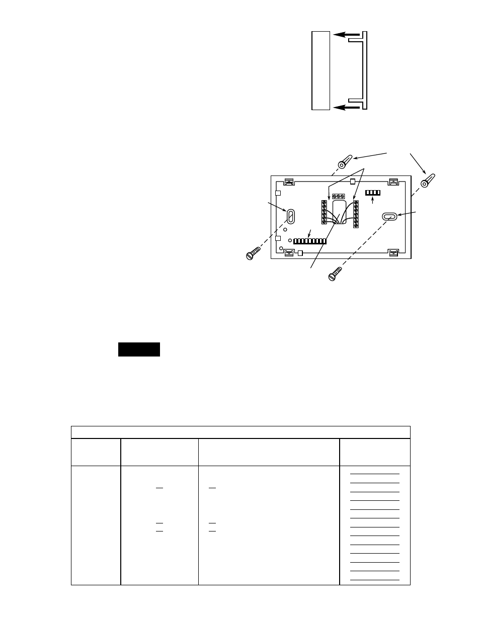
2.
Connect wires beneath terminal screws on subbase
using wiring schematic for your particular application
(see figs. 3 through 6).
3.
Place subbase over hole in wall and mark mounting
hole locations on wall using subbase as a template.
4.
Move subbase out of the way. Drill mounting holes.
5.
Fasten subbase loosely to wall, as shown in fig. 3,
using two mounting screws. Place a level against
bottom of subbase, adjust until level, and then tighten
screws. (Leveling is for appearance only and will not
PULL STRAIGHT OUT
Figure 2. Removing thermostat from subbase
NOTE
Mounting
hole
Pull wires through
this opening
Connect wires under
terminal screws
Mounting
hole
4-pin connector
9-pin connector
O
B
Y1
Y2
C
G
W1
R
W2
W3
Screw
anchors
Figure 3. Subbase
S1 S2 S3