Installation – Watlow Series 142 User Manual
Page 2
2
■
User’s Manual
Watlow Series 142
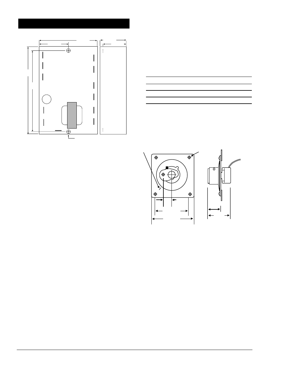
Figure 2a — Series 142 dimensions.
Installation Procedure
1. Drill two 5mm (0.187 in.) diameter holes in the desired
panel location.
2. Mount the unit with two 6-32 screws, 6mm (0.25 in.) hex
nut and #6 internal tooth lock washer.
3. Use the correct thermocouple type per the model num-
ber on the unit sticker. See the side of the case.
• Use correct thermocouple polarity. Red is negative.
• Insulate the thermocouple mounting from the mount-
ing surface to prevent heat migration input errors.
• Thermocouple leads should be twisted pair wire and
routed separately from any other lines.
• In electrically-noisy environments (heavy switching
contactors, motors, solenoids, etc.), use shielded ther-
mocouple lead wire with the shield connected at the
sensor end only.
• Use a separate thermocouple to maintain the limit
function of this controller; do not parallel thermocou-
ple input from the primary
controller.
4. All wiring and fusing must conform to the National
Electric Code (NEC) NFPA70 and any other locally
applicable codes.
5. Fuse the independent load voltage on the L1 (hot) side
and connect it to the common (C) side of the relay.
NOTE: For applications where the CE mark is required, all quick
connect and spade terminals must be pre-insulated to meet IEC
730 specifications.
Units With Remote Setpot Assembly
1. Drill two 51mm (2.0 in.) diameter holes in the desired
remote setpot assembly location. See Figure 2b.
2. Using the dial scale as a location template, center and
mark all four mounting holes on the dial scale with a
center punch.
3. For bolted dial scale assembly, drill four 3mm (0.125 in.)
diameter clearance holes. If you are using a screw
assembly, use a tap drill. Tap drill sizes used are:
Tap Drill Size
Screw/Thread Size
#44 - 2mm dia. (0.086 in.)
#4.36
#43 - 2mm dia. (0.089 in.)
#4.40
#42 - 2mm dia. (0.093 in.)
#4.48
4. Drill four 5mm (0.189 in.) diameter holes in desired
panel location. See Figure 2b.
5. Mount the Series 142 with four screws.
6. Connect sensor, load and remote setpot assembly per
Wiring Diagram. See the wiring pages.
Figure 2b — Setpot dimensions and mechanical zero
location.
Dial Scale Alignment to Mechanical Zero
1. Turn the dial scale knob completely counterclockwise (to
mechanical zero).
2. If the “Indicator” line on the setpot knob skirt, and
“Mechanical Zero” (represented by a small line beyond
the low end of the scale) are not aligned, loosen both set
screws on the setpot knob, and rotate the knob until
both lines meet.
3. Tighten both set screws.
13mm
(0.53 in.)
68mm
(2.69 in. sq.)
76mm
(3.00 in. sq.)
4 mounting holes
23mm
(0.9 in.)
Mechanical Zero
43mm.
(1.72 in)
103mm
(4.05 in.)
89mm
(3.50 in.)
Use a 6mm (0.25 in.) hex nut
for proper clearance.
Two 5mm (0.187 in.) dia.
mounting holes
35mm
(1.38 in.)
70mm
(2.76 in.)
35mm
(1.38 in.)
29mm.
(1.13 in)
Installation