Standard cable pinouts, P2 p1 – Welch Allyn IMAGETEAM 3800 User Manual
Page 114
IMAGETEAM 3800 User’s Guide
13–2
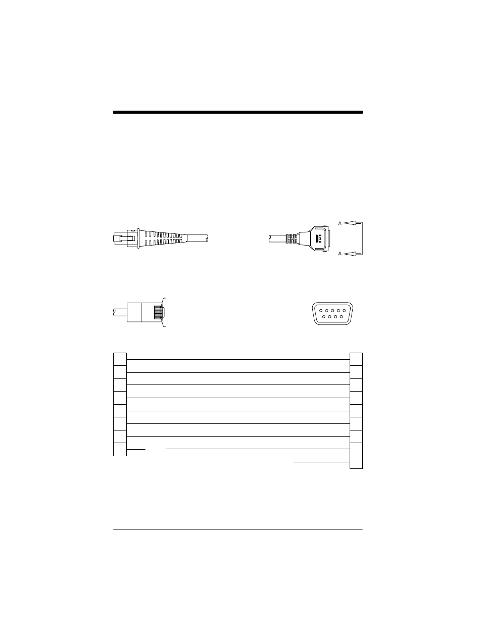
Standard Cable Pinouts
Laser Output only
(Laser Compatible Bar Image)
Conventional laser data format is provided at the modular connector in the
scanner handle.
Interface cables are terminated with a 10 pin modular plug (P1) and a 9 pin
Type D (squeeze to release) connector (P2) that is compatible with all Welch
Allyn Data Collection, Inc. terminals. See chart below.
Signal
Function
3
4
1
6
7
2
9
1
2
3
4
5
6
7
8
9
P2
P1
9 Pin Type D Female
10 Pin Modular Plug
Pin 1
Pin 10
6
9
1
5
N/C
Enable
Ground
Good Read
Data
+5VDC
Trigger
SOS
Cord Shield
Laser Enable
Supply Ground
Turn on Good Read LED or Beeper
Digital Bar Code Data Output
5 Volt Power Connection
Trigger Signal to Decoder
Start of Scan
Braid
P1
P2
View A–A
P2 connects to
your terminal.
P1 connects to the
scanner handle.
♦
Pins 4 and 9 are populated depending on power supply voltage option.
♦
♦
N/C
Note: Some decoders may have +12V on pins 4 or 9. Connect to +5VDC
ONLY!