Cast iron stove and burner system, Sdvbn(a) and sdvbp(a), General venting – Vanguard Heating SDVBN(A) User Manual
Page 8
8
®
CAST IRON STOVE AND BURNER SYSTEM
105499
SDVBN(A) AND SDVBP(A)
LOCATION OF VENT
TERMINATION
When locating vent termination, it is impor-
tant to observe the minimum clearances
shown in Figure 18, page 9.
*Check with local codes or with the current
CAN/CGA B149[.1 or .2] Installation Codes
for Canada or the USA Installations follow
the current National Fuel Gas Code, ANS
Z223.1, also known as NFPA 54.
These models are approved for use with
Simpson Dura-Vent 6
5
/
8
" direct-vent pipe
components and terminations as well as both
flex and rigid Vanguard vent components.
Your stove with burner system is approved
to be vented either through the side wall, or
vertically using the following guidelines:
• Only use Vanguard or Simpson Dura-
Vent GS venting components or kits spe-
cifically approved for this stove and
burner system.
• Minimum clearance between vent pipes
and combustible materials is 1" (25 mm),
except where stated otherwise.
GENERAL VENTING
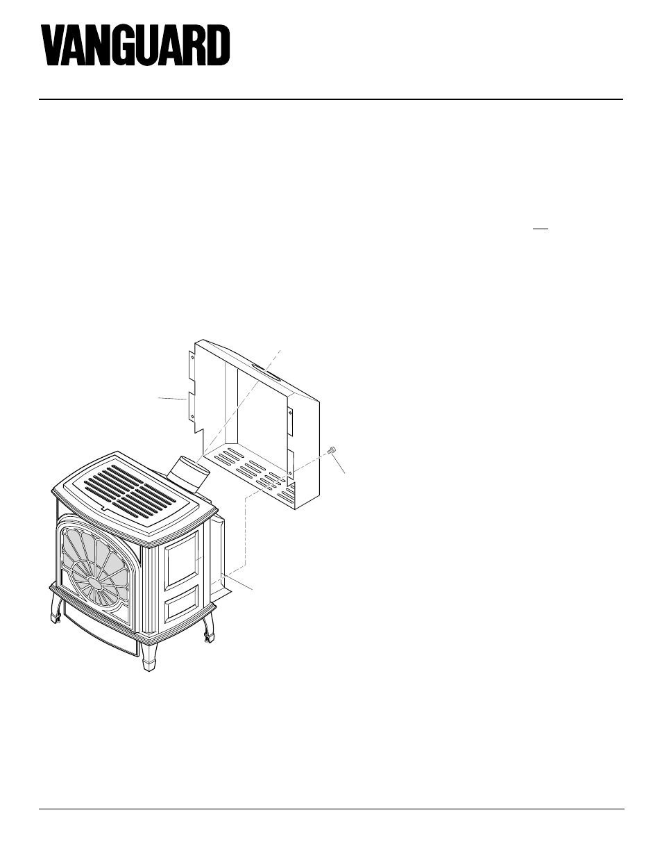
INSTALLING REAR COVER
1.
Lift rear panel over vent pipe connec-
tion on burner system. Rear cover will
rest on the bottom ledge of the stove
body.
2.
Using screws provided, attach rear cover
to back of stove body. See Figure 17.
IMPORTANT:
This rear cover must be
securely in place before venting pipes
are installed.
Figure 17 - Installing Rear Cover
CAST IRON STOVE
AND DIRECT-VENT
BURNER SYSTEM
ASSEMBLY
Continued
Rear
Cover
Burner System
Installed In Cast
Iron Stove Body
Screw
• Do not recess venting terminals into a
wall or siding.
• Install horizontal venting with a 1/4"
rise for every 12" of run toward the
termination.
• You may paint the vent terminal with
450ºF (232ºC) heat-resistant paint to co-
ordinate with the exterior finish.
• There must not be any obstruction such
as bushes, garden sheds, fences, decks,
or utility buildings within 24" from the
front of the termination cap.
• Do not locate termination cap where ex-
cessive snow or ice build up may occur.
Be sure to clear vent termination area af-
ter snow falls to prevent accidental block-
age of venting system. When using snow
blowers, do not direct snow towards vent
termination area.
• You must maintain minimum wall and
ceiling clearances shown in Figures 3 and
4, page 4.